
Nacelle nose cap forming method and apparatus

a technology of forming method and forming apparatus, which is applied in the direction of metal-working apparatus, stripping device, manufacturing tools, etc., can solve the problems of low yield and non-optimal process, and achieve the effect of less thinning, less time and stages, and less time and stages in forming

Active Publication Date: 2008-02-26
TEXTRON INNOVATIONS
View PDF8 Cites 20 Cited by
  • Summary
  • Abstract
  • Description
  • Claims
  • Application Information

AI Technical Summary

Benefits of technology

[0004]The principal object of the present invention is to provide a draw formed method for a nose cap having less thinning of the metal sheet and therefore more strength than the prior art nose caps.
[0006]A further object of the present invention is to provide a method of draw forming with only a minimum of forming stages rendering the process less arbitrary as to the intermediate forming stages and less heat treatments

Problems solved by technology

This process is non-optimal as the staging of the process is arbitrary and the process has a very high scrap rate between 50%-70% and, therefore, very low yield.

Method used


Image

  • Nacelle nose cap forming method and apparatus
  • Nacelle nose cap forming method and apparatus
  • Nacelle nose cap forming method and apparatus

Examples


Embodiment Construction

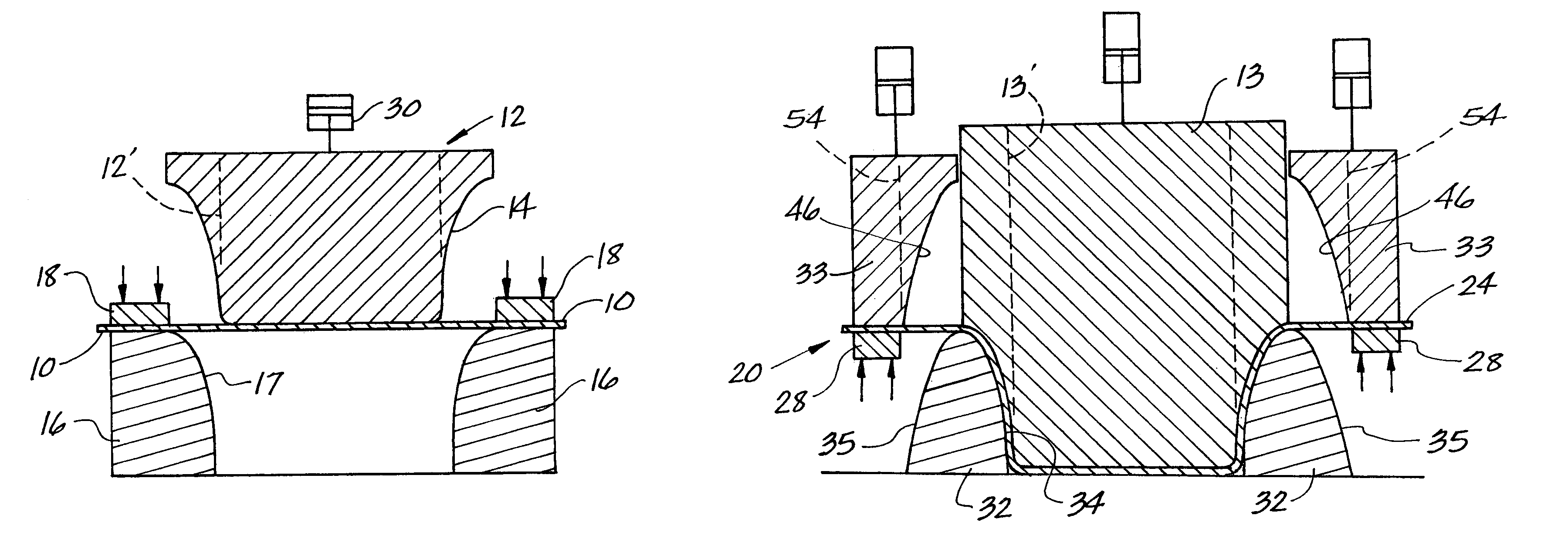
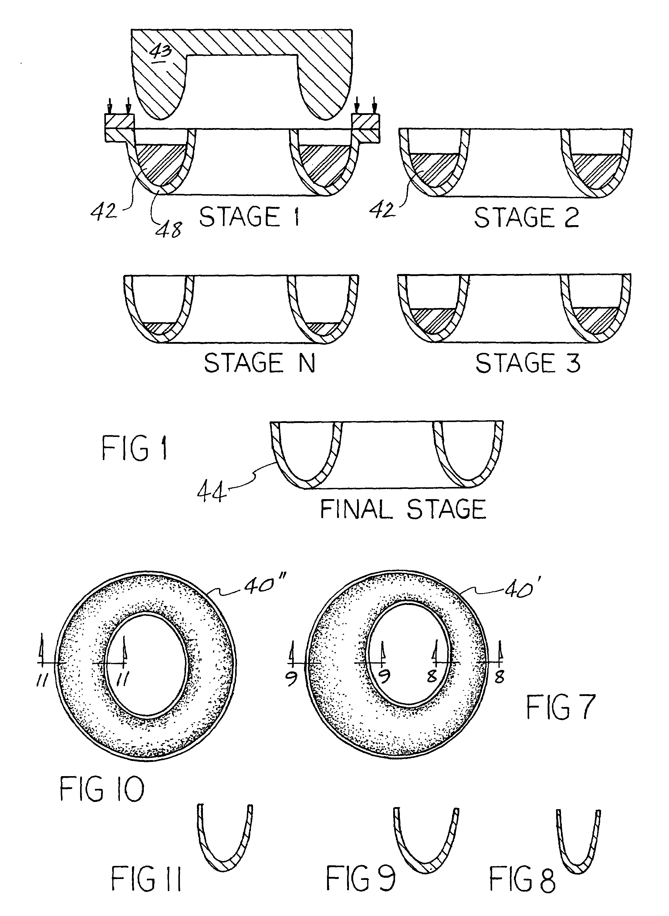
[0024]FIG. 1 illustrates the traditional prior art method of draw forming engine nacelle nose caps in multiple stages with intermediate heat treatments between stages. In stage 1 the die 48 is partially filled with a filling material such as rubber 42 to reduce its depth so that the punch 43 is only partially inserted in the die 48. In the stages 2, 3, etc. up to the final stage the amount of filling material is progressively reduced until there is no filler in the final stage 44 with heat treatments provided between stages. The number of stages and heat treatments can vary upwardly depending upon the part geometry and the operator forming the nose caps. Stages 1 through 3 are in a sense a hydroforming press in that there is no mating shaped female die but rather a flat layer of rubber that deforms to the shape of the male punch 43. The final stage is conventional draw forming where there are a pair of mating ridged dies which form the blank.

[0025]The present invention forming proce...


PUM

PropertyMeasurementUnit
Shapeaaaaaaaaaa
Areaaaaaaaaaaa

Abstract

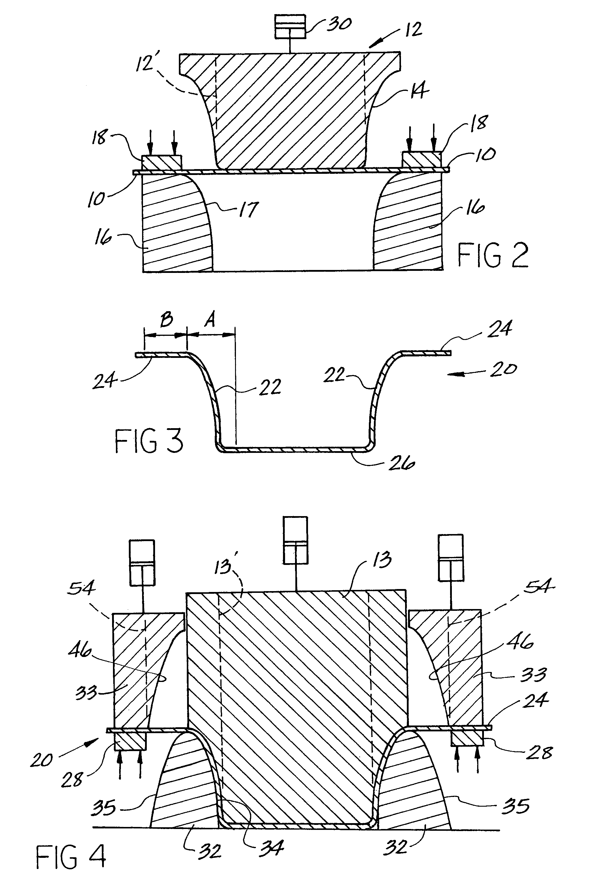
A method and apparatus for draw forming a flat sheet blank into a 3-dimensional-nacelle nose cap for an aircraft engine in two stages; the blank having an outer annular portion and an inner annular portion. Draw forming the inner annular portion into a shape of an arcuate circular inner wall and then draw forming the outer annular portion into an arcuate outer wall adjacent the inner wall with the combination of walls being U-shaped in cross section.

Description

FIELD OF THE INVENTION[0001]The present invention relates to a method and apparatus for deep drawing a metal blank and in particular to the forming process used to form nacelle nose caps for jet engines using aluminum alloy and steel alloy sheet metal.BACKGROUND OF THE INVENTION[0002]Traditionally, jet engine nose caps or nose cap rings are draw formed in multiple stages with intermediate heat treatments on a draw die or a hydro press or a combination of both. The tools represent the final part geometry in cross-section. The intermediate stages are formed by withdrawing the punch when it's partly immersed in the die. The punch travel is restricted by temporarily filling the die cavity with a filler material such as rubber, to reduce its depth. Generally sheets of flat rubber or custom fit resin plugs are used for this purpose. This process is non-optimal as the staging of the process is arbitrary and the process has a very high scrap rate between 50%-70% and, therefore, very low yie...

Claims


Application Information

Patent Timeline
IPC IPC(8): B21D22/00B21D31/00B21D45/00
CPCB21D22/24
Inventor KULKARNI, PRAVINSHASHIKIRAN, PRABHAKAR
Owner TEXTRON INNOVATIONS
Learn More