
Torque reaction control link

a torque arm and control link technology, applied in resilient suspensions, interconnection systems, vehicle components, etc., can solve the problems of difficult control of bump and roll steer of the axle as desired, limited design, and limited torque arm length of the side view swing arm (svsa), so as to minimize the conversion of sprung weight and minimize the change of pinion angle

Inactive Publication Date: 2008-02-26
DREHER JR GORDON A
View PDF7 Cites 3 Cited by
  • Summary
  • Abstract
  • Description
  • Claims
  • Application Information

AI Technical Summary

Benefits of technology

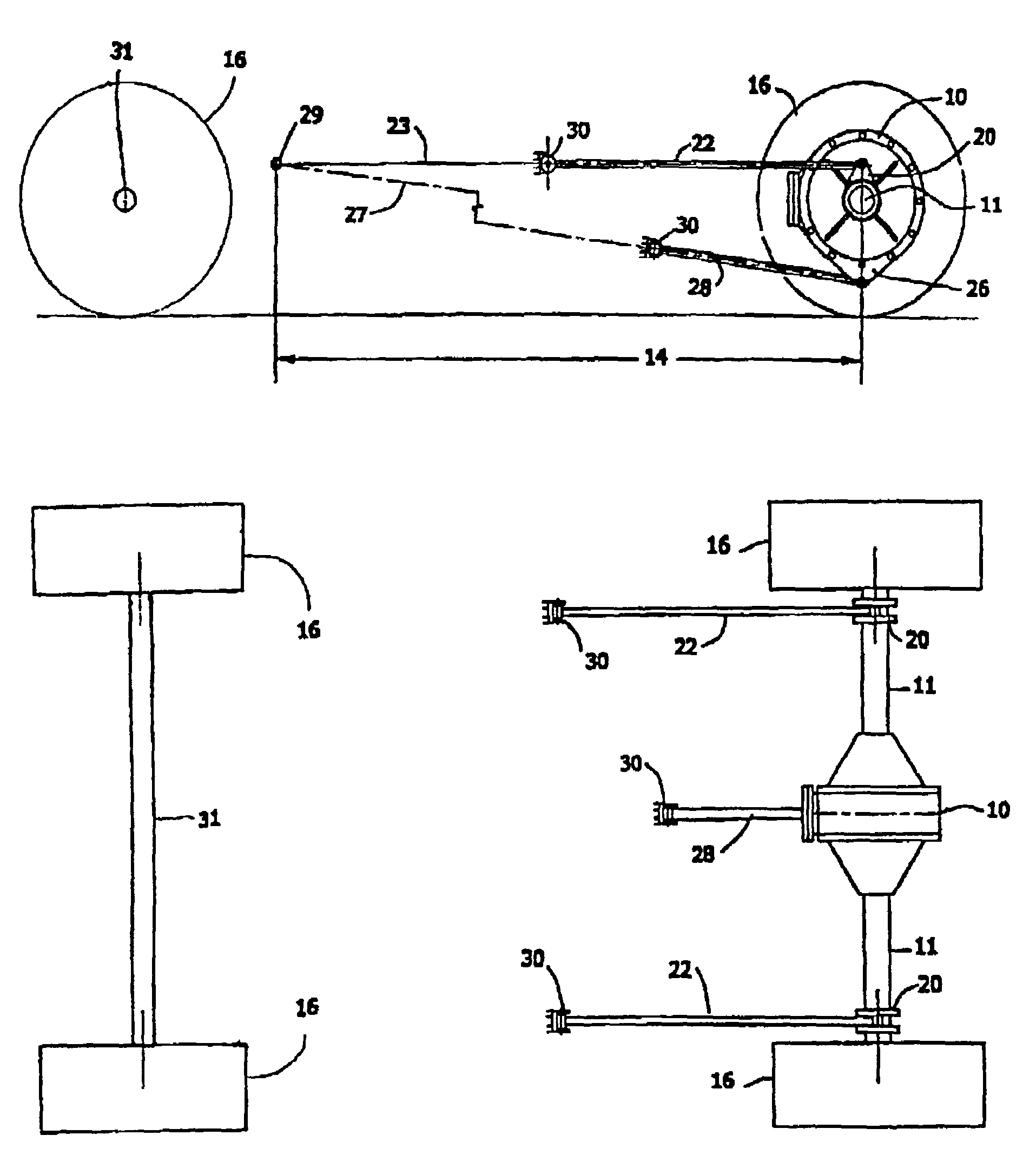
[0015]It is an object of the present invention to provide a torque reaction control link in a lower position than a torque tube or torque arm so that there is no intrusion into the vehicles body.
[0017]Still a further object of the present invention is to provide a torque reaction control link suspension that minimizes pinion angle change in the negative direction when the axle moves up vertically into a bump condition.
[0018]Still another object of the present invention is to provide a torque reaction control link suspension to minimize the conversion of sprung weight on the drive axle to an undamped vertical force on the tires.
[0019]Still another object of the present invention is to provide a torque reaction control link suspension for a rigid drive axle suspension that allows a vehicle to maintain traction of the drive axle tires when accelerating over irregular terrain.

Problems solved by technology

This design has severe limitations in that the complete axle housing has to pivot from the “ball” at the transmission in all planes.
This makes it difficult to control the bump and roll steer of the axle as desired.
This allows some design freedom, but still has limitations, in that there is no allowance for lateral shifting of the axle perpendicular to the torque tube.
A torque arm has limitations on the length of the side view swing arm (SVSA) because of the placement of the engine / transmission in the chassis of the vehicle.
All of these designs are limited, because the length of the torque tube or torque arm is restricted by the distance between the rigid drive axle and the transmission.
The lifting of the chassis at the end where the drive axle is located decreases the sprung weight and increases the undamped weight on the drive axle, thereby reducing the control of the axle by the shock absorbers, when the wheels and axle move vertically over irregular terrain.
This change in the negative direction of pinion angle causes forward rotational scrub of the tire contact patch on the ground, and when accelerating, a loss of traction.
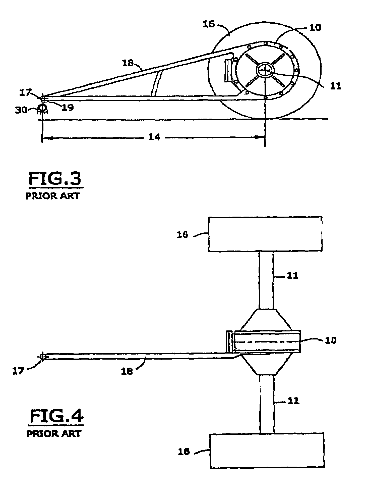
The problem with this design is the side view swing arm (SVSA) is relatively short and becomes shorter with the movement of the instant center toward the drive axle which causes an increase in the pinion angle change in the negative direction and the conversion of sprung weight on the drive axle to direct vertical force or undamped weight on the tires or road wheels thus decreasing the ability of the tires to maintain traction over irregular surfaces while accelerating.
This awkward configuration results in the instant center shifting from one end of the vehicle to the opposite end when the drive axle moves into a bump condition.
The problem with this design is that the when the drive axle moves into a bump condition the torque reaction of the axle when accelerating will pull the vehicle's chassis down at the drive axle decreasing available chassis clearance to the ground, drive axle clearance to the chassis and the springs and shock absorbers available stroke.
Another problem with this design is that it calls for the spring strut or shock absorber bearing the axle's reaction forces in a bending mode.
A significant deficiency with the previous developed solutions, as well as many other similar devices, is that they provide a vehicle suspension system that limits the ability of the vehicle's drive axle tires to maintain traction when accelerating over irregular terrain and / or puts the drive axle reaction forces on the spring strut or shock absorber rather than the axle attachment structures.

Method used


Image

  • Torque reaction control link
  • Torque reaction control link
  • Torque reaction control link

Examples


Embodiment Construction

[0029]This application claims priority of U.S. Provisional Patent Application 60 / 491,503, filed on Jul. 31, 2003, titled: Torque Reaction Control Link.

[0030]At the outset, it should be clearly understood that like reference numerals are intended to identify the same structural elements, portions, or surfaces consistently throughout the several drawing figures, as may be further described or explained by the entire written specification of which this detailed description is an integral part. These embodiments should not be construed as the only applications that the inventions may be used.

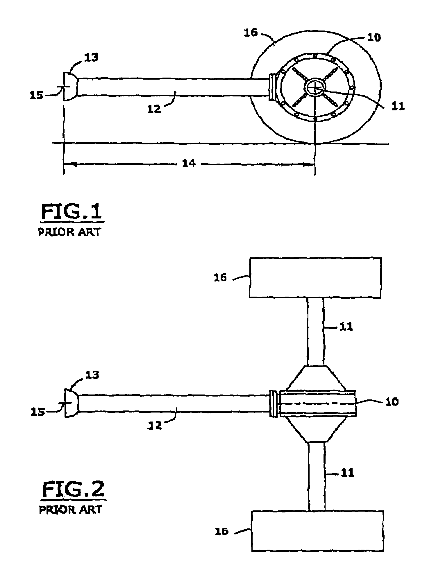
[0031]A significant deficiency with the previously developed suspension systems such as those depicted in FIGS. 1-4, as well as many other similar devices, is that they provide a vehicle suspension system that limits the ability of the vehicle drive axle tires to maintain traction when accelerating over irregular terrain and / or puts the drive axle reaction forces on the spring strut or shock absorbe...


PUM


Abstract

A suspension system for a motor vehicle comprising a chassis, a rigid drive axle, an opposite axle and road wheels attached to the ends of each axle, a torque reaction control link positioned longitudinally of the motor vehicle with longitudinal control arms pivotally attached to the rigid drive axle, for controlling torque reaction of the rigid drive axle, in combination with the torque reaction control link. The torque reaction control Link has a longitudinal plane that extends longitudinally of the motor vehicle and whereby the effective projection lines of the longitudinal control arms and the longitudinal plane of the torque reaction control link Intersect each other forming a convergent angle at an instant center located closer to the opposite axle than to the rigid drive axle and that when a force moves the rigid drive axle vertically up the convergent angle does not increase.

Description

BACKGROUND OF THE INVENTION[0001]1. Field of Invention[0002]This invention relates to a rigid drive axle suspension system for motor vehicles.[0003]2. Description of Prior Art[0004]Typically, as part of an automobiles suspension, the driveshaft between the engine / transmission and the rigid drive axle gear housing is enclosed in a “torque tube.” The torque tube is rigidly attached to a drive axle / gear housing assembly at one end and the other end has a “ball” that is enclosed by “ball drive housing” that is attached to the output end of the transmission. Inside the “ball” is the universal joint that rotates the driveshaft inside the “torque tube.” At the axle gear housing the driveshaft rotates the pinion gear through a straight splined coupling.[0005]This design has severe limitations in that the complete axle housing has to pivot from the “ball” at the transmission in all planes. This makes it difficult to control the bump and roll steer of the axle as desired.[0006]Presently, many...

Claims


Application Information

Patent Timeline
Patent Type & Authority Patents(United States)
IPC IPC(8): B60G9/00B60G7/00B60G9/02
CPCB60G7/001B60G7/008B60G9/003B60G9/027B60G11/10B60G2200/31B60G2200/324B60G2204/148B60G2206/11
Inventor DREHER, JR., GORDON A.
Owner DREHER JR GORDON A
Learn More