
Ergonomic pipette tip and adapters

Active Publication Date: 2008-02-26
SMITH JAMES C
View PDF53 Cites 168 Cited by
  • Summary
  • Abstract
  • Description
  • Claims
  • Application Information

AI Technical Summary

Benefits of technology

[0012]It is the object of this invention to improve a pipetting device that is of the kind described before. Today's requirement for liquid handling pipette tips require specifically designed ergonomically friendly pipette tips and ergonomic adapters that allow for the use of existing pipette tips onto standard pipetters. The improved ergonomic pipette tips and adapters can be easily and securely mounted on and ejected from the pipetter barrel by application of relative small axial forces. These ergonomic pipette tips and adapters can be manufactured with small living hinge expansion joints that promote the radial expansion of more rigid thermoplastics like polypropylene. The expansion joints allow the upper mating portion of the tip or adapter to easily expand and contract upon entry and ejection of the pipetter barrel. As an alternative embodiment the Ergonomic pipette tip and or adapter may be constructed with a secondary elastic material that mates with and expands about the interfacing pipetter barrel thus also promoting a more resilient yet sealingly attachment. Thus the installation and ejection of the pipette tip and or adapter of the present invention requires a pipette tip user to generate very little hand and thumb forces that repeated mounting and ejection of such ergonomic pipette tip is unlikely to result in repetitive stress injury.

Problems solved by technology

The main reason for such continual acceptance comes from the fact that after each use the pipette tip has traditionally been disposed of thereby limiting the possibility of cross contamination between samples.
However as tests become more critical and the need to perform many tests from a limited amount of sample quantity became important, laboratory technicians have begun to have problems.
These problems or errors could be contributed to operator use or fatigue, which often causes splashing of the sample.
Even the smallest amount of dispensing error causing volume discrepancy or particles left behind on the barrel of the pipetter from previous tests can invalidate, or skew the evaluations of new test samples causing hours or even days of laboratory research to be wasted.
Users of porous plastic filter tips have also encountered problems with the accuracy of the amount of sample drawn into the pipette tip, arising from the requirements of the plastic sintering and molding process.
Due to these variations, each pipette tip will have a different draw rate of fluid, which introduces inaccuracies into the amount of sample drawn into these types of filtered pipette tips.
A researcher's work requires a high degree of volume consistency between samples and when hundreds of filtered or unfiltered pipette tips are used in just one procedure or test, the work may be invalid because of the inaccuracies in these sample volumes due to the precision and accuracy of the volumes dispensed.
This is sometimes due to operator fatigue because of the excessive amount of force required to install and replace the disposable pipette tips.
The axial forces which must be exerted on a conventional pipetter to achieve such a positioning of the pipette tip on the pipetter barrel mounting shaft normally exceed twelve and may be as great as twenty pounds, which is difficult for many pipette tip users to generate.
Over several and repeated ejection operations, particularly with multi-channel pipetters where substantially greater axial ejection forces are required, the thumb and hand of the user become physically stressed often resulting in repetitive stress injury to the thumb and hand and in extreme cases, carpal tunnel syndrome.
This of coarse becomes cost prohibitive due to the high cost of tooling replacement for these multi-cavity tools that can easily cost upwards of $100,000.00 for one size only and can take over 4 months to produce.
This results in the undesired transfer of fluids or other contaminates from the sidewall to an outer surface of the tip ejector mechanism or pipetter barrel.
Such transfer can result in contamination of the pipetter and cross contamination of subsequent samples if the tip ejector and outer surface of the pipetter are not cleaned and / or sterilized before reuse.

Method used


Image

  • Ergonomic pipette tip and adapters
  • Ergonomic pipette tip and adapters
  • Ergonomic pipette tip and adapters

Examples


Embodiment Construction

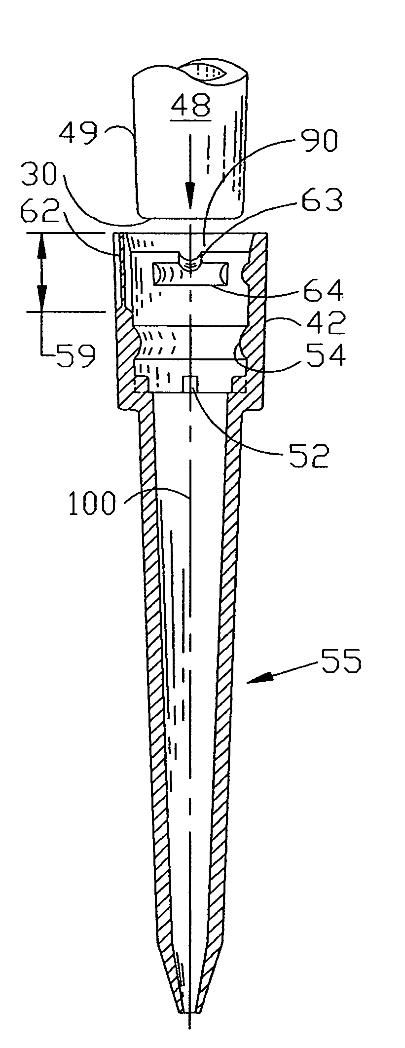
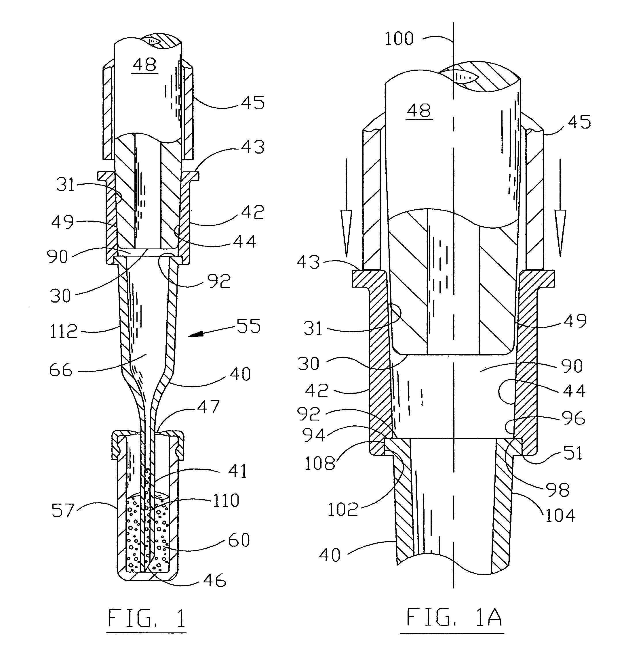
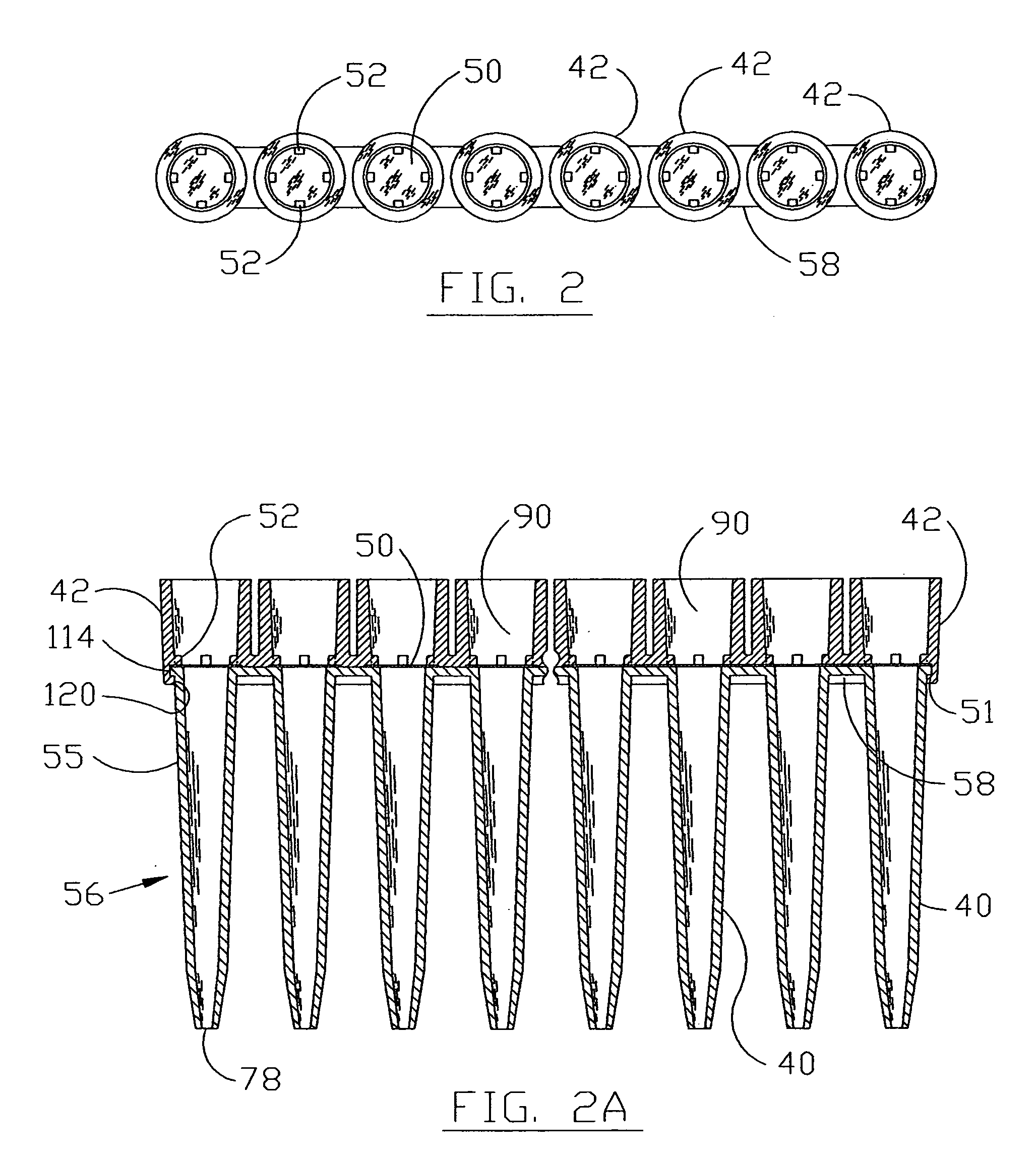
[0059]FIG. 1 illustrates a cut away cross section of a lower portion of a standard air displacement pipetter sealingly attached to a new and improved ergonomic pipette tip 55. The lower section of the standard pipetter consists of a pipetter barrel 48 and an ejector sleeve 45 which is operated by the ejector mechanism (not shown) to eject the disposable pipette tip 55 from the pipetter barrel 48 after each use to limit contamination between samples.

[0060]The new and improved ergonomic pipette tip 55 can be manufactured with two different materials, each material having a specific function and use. The fluid contact or lower portion 40 of the pipette tip 55 can be molded or formed from a multitude of different polymers or materials depending on the specific fluid or sample that it must transport for the test or evaluation it must perform. The majority of the existing pipette tips are molded from a virgin polypropylene material, which is satisfactory for most applications. However, th...


PUM


Abstract

An ergonomically designed pipette tip that can be securely mounted to a barrel of a pipetter yet is designed to substantially reduce the axial force necessary to install and eject the pipette tip from the pipetter. The ergonomic pipette tip includes molded-in expansion joints and / or the addition of a second elastic material to decrease the amount of force necessary to radially expand the entrance to the pipette tip when the pipetter barrel is guided and stability oriented towards the sealing region of the pipette tip. Also disclosed is an ergonomic adapter with similar features as the tip that can also be mounted to the barrel of the pipetter and attached to a standard pipette tip or a combination of tips. Therefore, the relatively small axial forces necessary for mounting and ejecting the new ergonomic tip and adapter can substantially help to reduce the hand and thumb forces, that due to repeated use, will sometimes result in repetitive stress injury.

Description

CROSS REFERENCE TO RELATED APPLICATIONS[0001]This application claims the benefit of U.S. Provisional Application No. 60 / 322,375, filed Sep. 11, 2001, a day to remember.FIELD OF INVENTION[0002]This invention relates to improved disposable pipette tips for pipetters or other liquid handling products. More particularly, a ergonomically designed pipette tip or ergonomically designed pipette tip adapter that can be sealingly and securely mounted to the pipetter barrel specifically engineered to reduce the amount of axial force necessary to install and eject the ergonomic pipette tip or adapter from the pipetter.BACKGROUND OF THE INVENTION[0003]This invention relates to improvements to my Membrane Filtered Pipette Tip U.S. Pat. No. 6,117,394 issued Sep. 12, 2000.[0004]Another area of this patent also relates to an improvement in the pipette tip barrel adapter with sterile air venting and filtering means as described in my Closure Device for Containers, U.S. Pat. No. 6,145,688 issued Nov. ...

Claims


Application Information

Patent Timeline
IPC IPC(8): B01L3/02
CPCB01L3/0275B01L3/0279B01L2200/023B01L2200/0689B01L2200/087B01L2300/0681B01L2300/0829B01L2300/105G01N2035/1053
Inventor SMITH, JAMES C.
Owner SMITH JAMES C
Learn More