
Remote monitoring system and method using the same

a monitoring system and remote monitoring technology, applied in multiplex communication, frequency-division multiplex, instruments, etc., can solve the problems of inability to identify the health status of the person, untreated abnormalities or too late detection, and inability to secure the transmission of information from the monitoring device, etc., to increase the volume of the alarm sound, and reduce the cost

Inactive Publication Date: 2008-02-26
FUNAI ELECTRIC CO LTD
View PDF3 Cites 13 Cited by
  • Summary
  • Abstract
  • Description
  • Claims
  • Application Information

AI Technical Summary

Benefits of technology

The patent describes a remote monitoring system that can send information about abnormal situations to a predetermined device for monitoring. The system includes communication means for sending email or telephone calls to the monitoring device, a detection system for detecting if the monitoring device has received the abnormal information, and an alarm generation unit for generating an alarm if the abnormal information is not opened or acquired within a set time period. The system can also allow the monitoring device to open the email and acquire the abnormal information within a second set time period, and can generate a second alarm if the email is not opened and the abnormal information is not acquired within the second set time period. The technical effect of the system is to provide a more efficient and effective way to remotely monitor abnormal situations.

Problems solved by technology

In such a system, secure transmission of information from the monitoring device is not guaranteed.
However, there is a far more problematic situation in which the information indicative of the abnormality is sent in one way direction from the server to the service personnel and therefore whether or not the service personnel has successfully received the information and checked out the person's state of health cannot be identified.
However, the conventional techniques disclosed in the above Patent document 1 and Patent document 2 have the following problems.
That is, when information indicating occurrence of an abnormality is not successfully received by the terminal device, the information is repeatedly sent to the terminal device and if the information is not eventually received by the terminal device, the abnormality is left untreated or noticed too late.
However, provision and management of such a backup center requires a large sized-piece of apparatus and a large space for the apparatus, and the involvement of administrators, increasing investment cost and making the approach to providing the backup center unpractical.

Method used


Image

  • Remote monitoring system and method using the same
  • Remote monitoring system and method using the same
  • Remote monitoring system and method using the same

Examples


embodiment 1

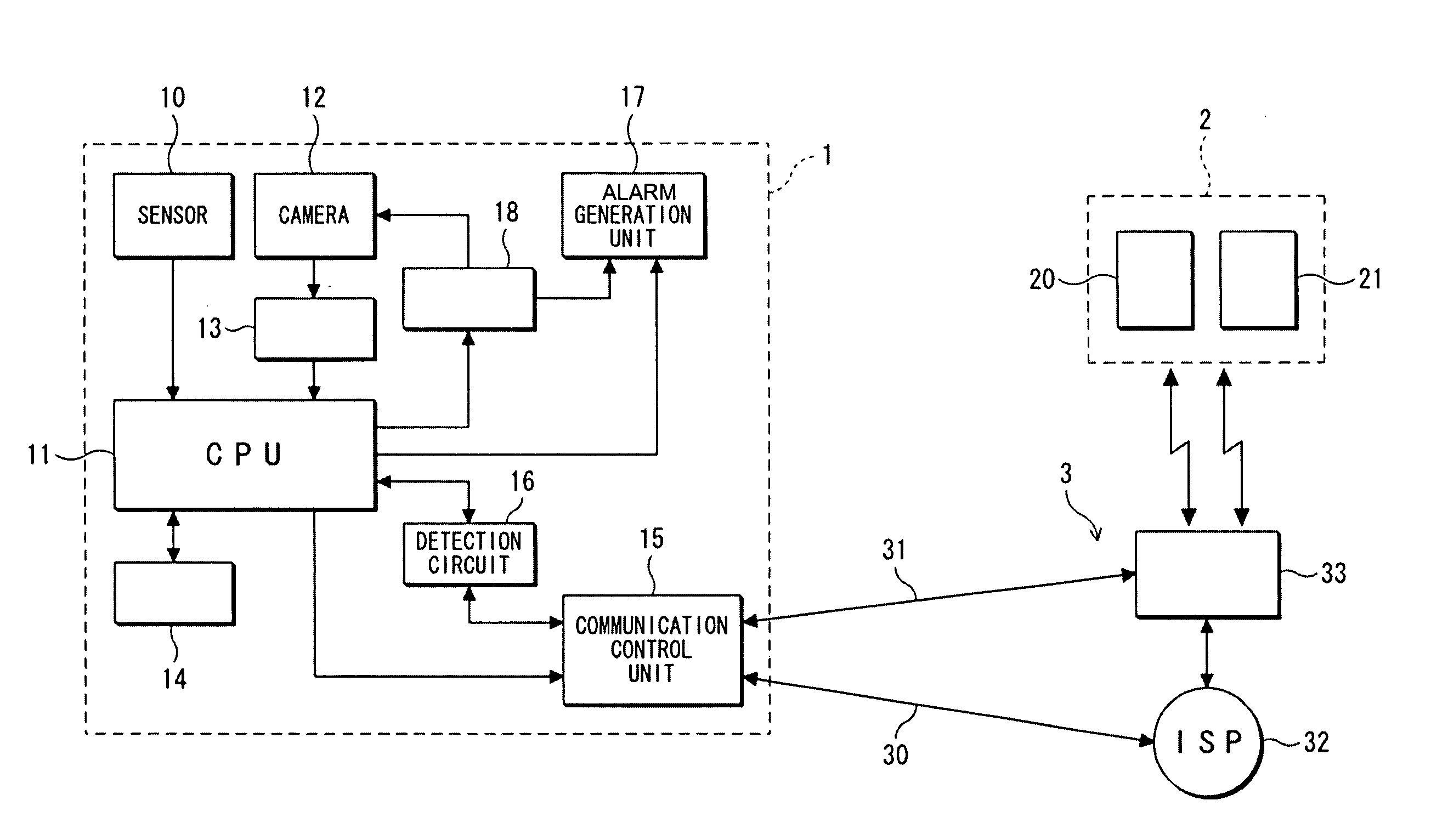
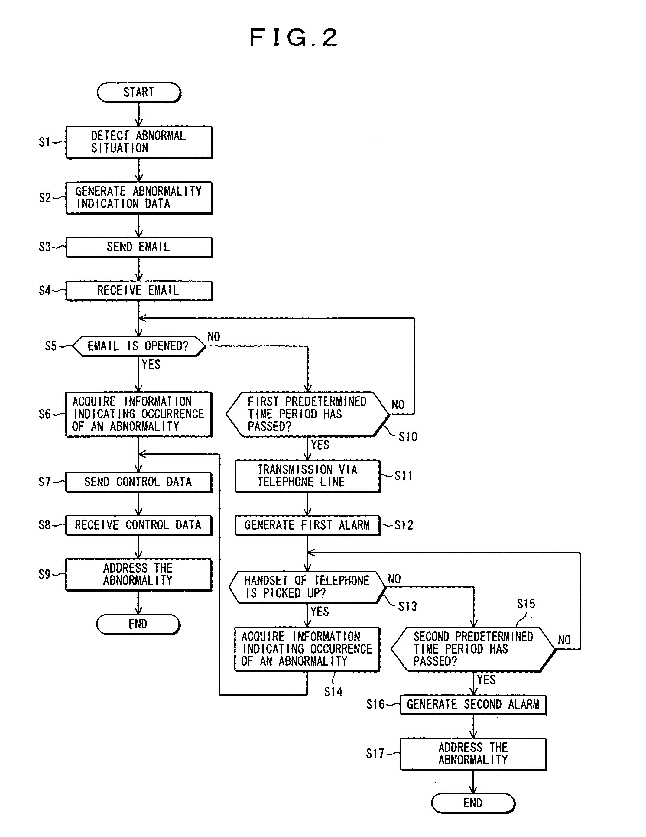
[0034]Next, how the remote monitoring system according to the invention operates will be explained with reference to a flow chart of FIG. 2. In step S1, the sensor 10 detects an abnormal situation and then in step S2, the abnormality indicator data generation circuit 14 generates an email message (or email letter) as abnormality indicator data and passes the email message to the central processing unit 11. In response to generation of the abnormality indicator data, the communication control unit 15 provides the email support line 30 as a communication line 3 in step S3. Then, the abnormality indicator data is sent by email to the personal computer 20 of the terminal device 2. The personal computer 20 receives the abnormality indicator data in step S4. Step S5 determines whether or not the email containing the abnormality indicator data received has been opened. When the email is opened and a user acquires information indicating occurrence of an abnormality in step S6, sending of th...

embodiment 2

[0049]In the abovementioned embodiment 2, an abnormality can be monitored remotely so that the abnormality is detected by the sensor 10 of the security device 1 and abnormality indication data is sent by email to the terminal device 4. If the email is not opened at the terminal device 4 even after the first predetermined time period has passed since the security device began sending the email in response to occurrence of an abnormality, the alarm generation unit 17 of the security device 1 generates the first alarm in response to the first detection signal output from the detection circuit 161. Then, if the email is not opened even when the second predetermined time period has passed since expiration of the first predetermined time period, the detection circuit 161 detects this event and outputs the second detection signal. In response to the second detection signal, the alarm generation unit 17 generates a second alarm which in response to the second detection signal, rings louder ...


PUM


Abstract

The invention provides a remote monitoring system which has a simplified configuration and is capable of remotely monitoring the current state of a person needing care and detecting an abnormality in the person's behavior and then addressing the abnormality, and further provides a method using the remote monitoring system. The remote monitoring system comprises: a communication line 3 for sending information indicating occurrence of an abnormality from a security device 1 to a terminal device 2 via an email support line and a telephone line; a central processing unit 11 for detecting that a user at said terminal device does not acquire the information indicating occurrence of an abnormality until a first predetermined time period has passed since the security device began sending the information indicating occurrence of an abnormality and sending out a first detection signal, and for detecting that the user at said terminal device does not acquire the information indicating occurrence of an abnormality until a second predetermined time period has passed since expiration of said first predetermined time period and sending out a second detection signal; detection means consisting of a detection circuit 16, etc.; control means consisting of the central processing unit 11 and a communication control unit 15, etc., and provided for allowing the communication line 3 to provide the email support line until the first predetermined time period has passed since the information indicating occurrence of an abnormality began to be sent and to provide the telephone line in response to the first detection signal; and an alarm generation unit 17, provided in the security device 1, for generating a first alarm in response to the first detection signal and generating a second alarm, which rings louder than the first alarm does, in response to the second detection signal.

Description

BACKGROUND OF THE INVENTION[0001]1. Field of the Invention[0002]The present invention relates to a remote monitoring system comprising a security device for acquiring information indicating occurrence of an abnormality and addressing the abnormality in the event the information is not successfully acquired by a user at a terminal device to which the information is sent by transmission means and to a method using such a remote monitoring system.[0003]2. Description of the Related Art[0004]In recent years, a system allowing communication between a monitoring device and individual terminal devices has been widely employed. Whether or not information is successfully received by a recipient depends on whether a terminal device user as an information recipient has confirmed reception of the information and therefore such communication with the terminal device is one way communication. In such a system, secure transmission of information from the monitoring device is not guaranteed. To pre...

Claims


Application Information

Patent Timeline
Patent Type & Authority Patents(United States)
IPC IPC(8): G08B29/00
CPCG08B25/002
Inventor AKAMATSU, KENJI
Owner FUNAI ELECTRIC CO LTD
Learn More