Distributed control system with multiple control levels and/or downloading

a control system and control level technology, applied in the field of distributed monitoring and control systems, can solve the problems of large, centrally-located and expensive computer systems, limited expansion capabilities, and large number of controlled devices which can be controlled by the field controller, and achieve the effect of easy increase or decrease of the number of controlled devices

Inactive Publication Date: 2008-02-26
SCHNEIDER ELECTRIC SYST USA INC
View PDF56 Cites 41 Cited by
  • Summary
  • Abstract
  • Description
  • Claims
  • Application Information

AI Technical Summary

Benefits of technology

[0007]A benefit of this arrangement is that the number of controlled devices which can be controlled by the field controller be easily increased or decreased by adding expansion module segments to, or removing them from, the field controller. Since the bus created by the series of bus segments is an extensible multi-drop bus, the controlled devices can be connected to the field controller through any interface module connected into the field controller along the bus. Since the processor module segment and each expansion module segment also includes an integral housing segment, when the processor module segment and expansion module segments are connected together they provide a unitary, compact housing which is convenient in a commercial, industrial or home environment.

Problems solved by technology

Typical distributed control systems essentially comprise large, centrally-located and expensive computer systems.
A number of problems arise out of use of such computer systems, including the facts that they are expensive to maintain and typically have limited expansion capabilities.

Method used


Image

  • Distributed control system with multiple control levels and/or downloading
  • Distributed control system with multiple control levels and/or downloading
  • Distributed control system with multiple control levels and/or downloading

Examples


Embodiment Construction

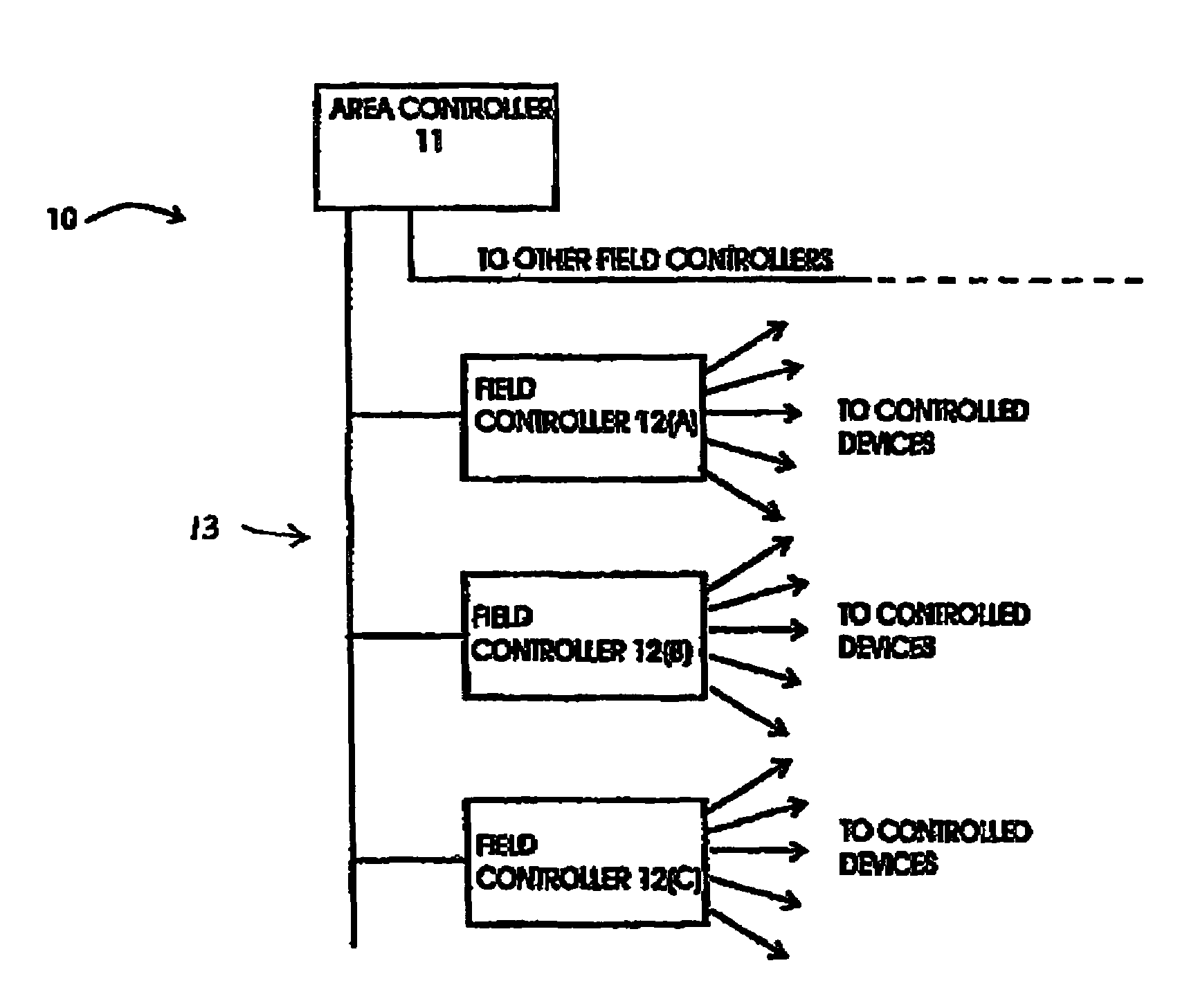
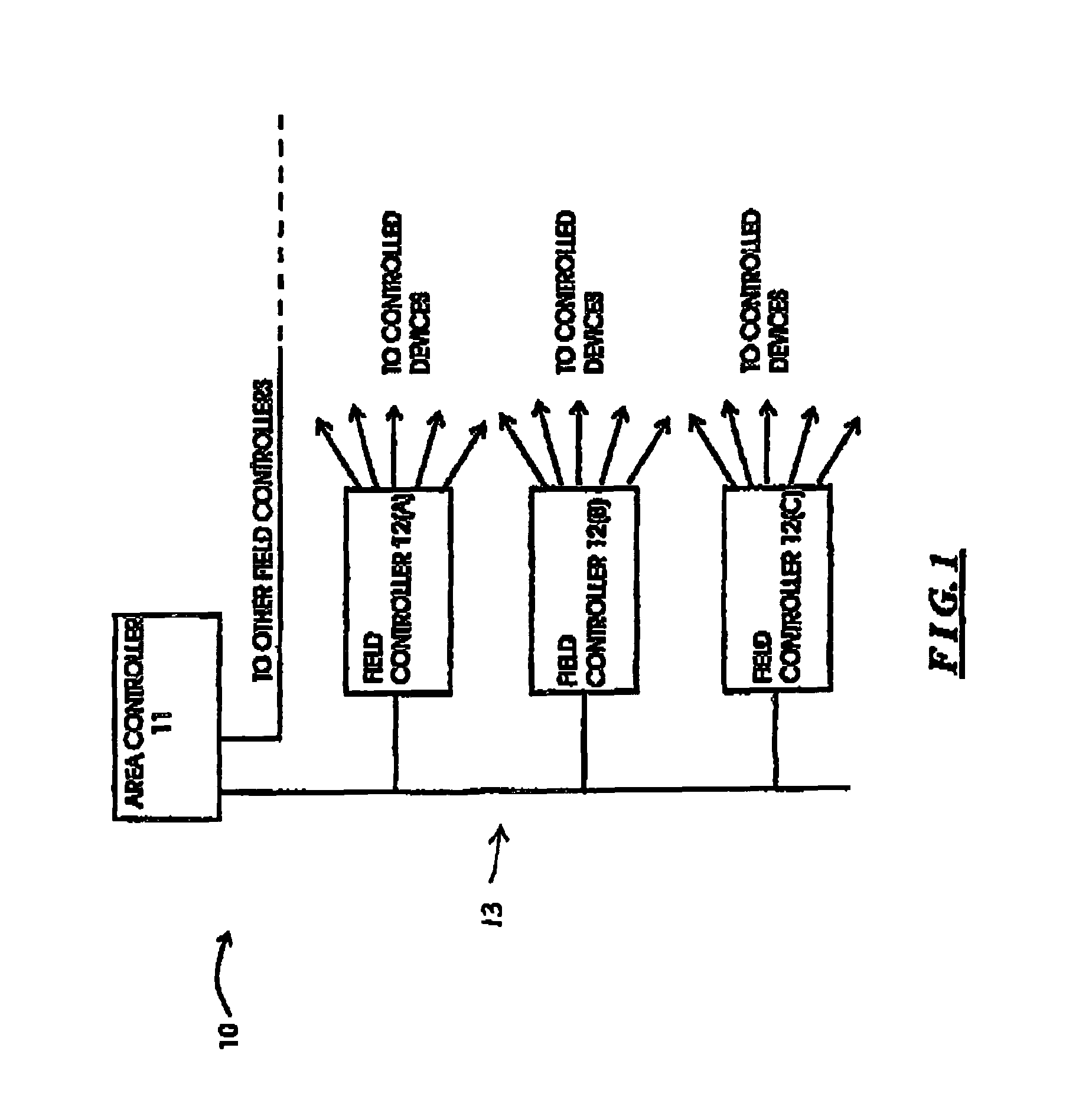
[0017]FIG. 1 is a functional block diagram of a distributed control system 10 which includes a field controller constructed in accordance with the invention. The distributed control system 10 may be used, for example, in a number of commercial, industrial and home applications, in particular to monitor and control a variety of diverse types of operations. For example, in a manufacturing operation, the distributed control system 10 may, for example, control various machines and robots to facilitate manufacture of those components that are manufactured on site, and transfer of the components from inventory to assembly locations where they are assembled into the final product. In such an operation, the distributed control system 10 will also receive status information regarding the operational status of the various machines controlled by the system, as well as, for example, the inventory of the various components which may be used in manufacture of the end product and the assembly line...


PUM


Abstract

A field controller for use in a distributed control system including an area controller and at least one field controller. The field controller manages at least one controlled device in an industrial process operation. The field controller comprises a processor module segment through which it can control a selected number of devices, and it may also include one or more expansion module segments to enable it to control a larger number of controlled devices. The processor module segment includes a processor module and at least one local interface module for interfacing to a controlled device, and the expansion module segment includes interface modules for interfacing to other controlled devices. In the processor module segment, the processor module and said local interface module are interconnected by a bus segment, which is also connected to an upstream off-module connector. Each expansion module segment includes at least one interface module, and also includes a downstream off-module connector and an upstream off-module connector, which are interconnected by a bus segment. The downstream off-module connector of each expansion module segment is adapted to mate with the upstream off-module connector of the processor module segment and of other expansion module segment, so as to facilitate the interconnection of the processor module segment and a sequence of expansion module segments by establishing a unitary multi-drop bus comprising the processor module's bus segment and the bus segments of expansion module in the sequence. The processor module controls each controlled device through the respective local interface module or expansion interface module connected thereto. The processor module segment and each expansion module segment are each mounted in a housing segment which is configured to form a unitary housing when they are interconnected.

Description

[0001]This application is a continuation of U.S. Ser. No. 09 / 528,263, filed Mar. 17, 2000 now U.S. Pat. No. 6,671,763, entitled “DISTRIBUTED CONTROL SYSTEM INCLUDING A COMPACT EASILY-EXTENSIBLE AND SERVICEABLE FIELD CONTROLLER,” which is a continuation of U.S. Ser. No. 09 / 443,774, filed Nov. 19, 1999 now U.S. Pat. No. 6,324,607, entitled “DISTRIBUTED CONTROL SYSTEM INCLUDING A COMPACT EASILY-EXTENSIBLE AND SERVICEABLE FIELD CONTROLLER,” which is a continuation of Ser. No. 08 / 560,167, originally filed Nov. 20, 1995 now U.S. Pat No. 6,076,124, and on which a continued-prosecution-application was filed Nov. 18, 1999, entitled “DISTRIBUTED CONTROL SYSTEM INCLUDING A COMPACT EASILY-EXTENSIBLE AND SERVICEABLE FIELD CONTROLLER,” which claims the benefit of priority of U.S. Ser. No. 60 / 005,279, filed Oct. 10, 1995, entitled “DISTRIBUTED CONTROL SYSTEM INCLUDING A COMPACT EASILY-EXTENSIBLE AND SERVICEABLE FIELD CONTROLLER.”FIELD OF THE INVENTION[0002]The invention relates generally to the fi...

Claims


Application Information

Patent Timeline
Patent Type & Authority Patents(United States)
IPC IPC(8): G06F13/00G06F13/12G05B15/02G05B19/042G05B19/05G05B19/418H01R9/26
CPCG05B19/0423G05B19/4185H01R9/2658G05B2219/25314G05B2219/25322G05B2219/25335G05B2219/25336G05B2219/25428G05B2219/31121G05B2219/33179G05B2219/33273G05B2219/33279G05B2219/34436Y02P90/02
Inventor KOROWITZ, SIMONKAGAN, HARRIS D.LAKE, HAROLD
Owner SCHNEIDER ELECTRIC SYST USA INC
Why Eureka
Try Eureka