
Diesel exhaust system variable backpressure muffler

a diesel exhaust system and variable backpressure technology, applied in the field of diesel exhaust systems, can solve the problems of increasing the temperature of tailpipe exhaust gas exit, unable to adequately burn away soot under all vehicle operating conditions, and damage to the engine or the engine, so as to reduce the amount of exhaust heat, reduce the amount of extra fuel injected, and increase the load of the engin

Inactive Publication Date: 2008-03-04
GM GLOBAL TECH OPERATIONS LLC
View PDF6 Cites 24 Cited by
  • Summary
  • Abstract
  • Description
  • Claims
  • Application Information

AI Technical Summary

Benefits of technology

The present invention provides an exhaust system for a vehicle with a diesel engine that includes a diesel particulate filter, an intermediate pipe with a main flow portion and a restricted flow portion, and a muffler. The system also includes a particulate filter backpressure valve and a restriction in the restricted flow portion of the intermediate pipe. The invention allows for regeneration of the particulate filter without adding a separate heater and minimizing extra fuel injected into the exhaust stream. The system also provides optimized exhaust noise for both the normal mode of driving and the regeneration mode of operation. The invention creates sufficient backpressure to cause regeneration in the diesel particulate trap while minimizing any increase in the temperature of the exhaust gasses as they exit the tailpipe.

Problems solved by technology

A clogged filter can potentially cause damage to itself or the engine.
However, while passive regeneration is desirable, it cannot be counted on to sufficiently burn away the soot under all vehicle operating conditions.
Moreover, this type of regeneration has the affect of raising tailpipe exhaust gas exit temperatures much higher than is typically experienced under normal operating conditions.
These temperatures may possibly rise to a level that is environmentally undesirable.
Also, for vehicles with the added diesel particulate filter, the filter regeneration mode of engine operation may create noise in the exhaust that is different or louder than that produced during the normal mode of engine operation.
Consequently, a conventional muffler may have reduced effectiveness in reducing unwanted noise emissions from the exhaust system during both the normal vehicle mode of operation and during the regeneration mode of operation.

Method used


Image

  • Diesel exhaust system variable backpressure muffler
  • Diesel exhaust system variable backpressure muffler
  • Diesel exhaust system variable backpressure muffler

Examples


Embodiment Construction

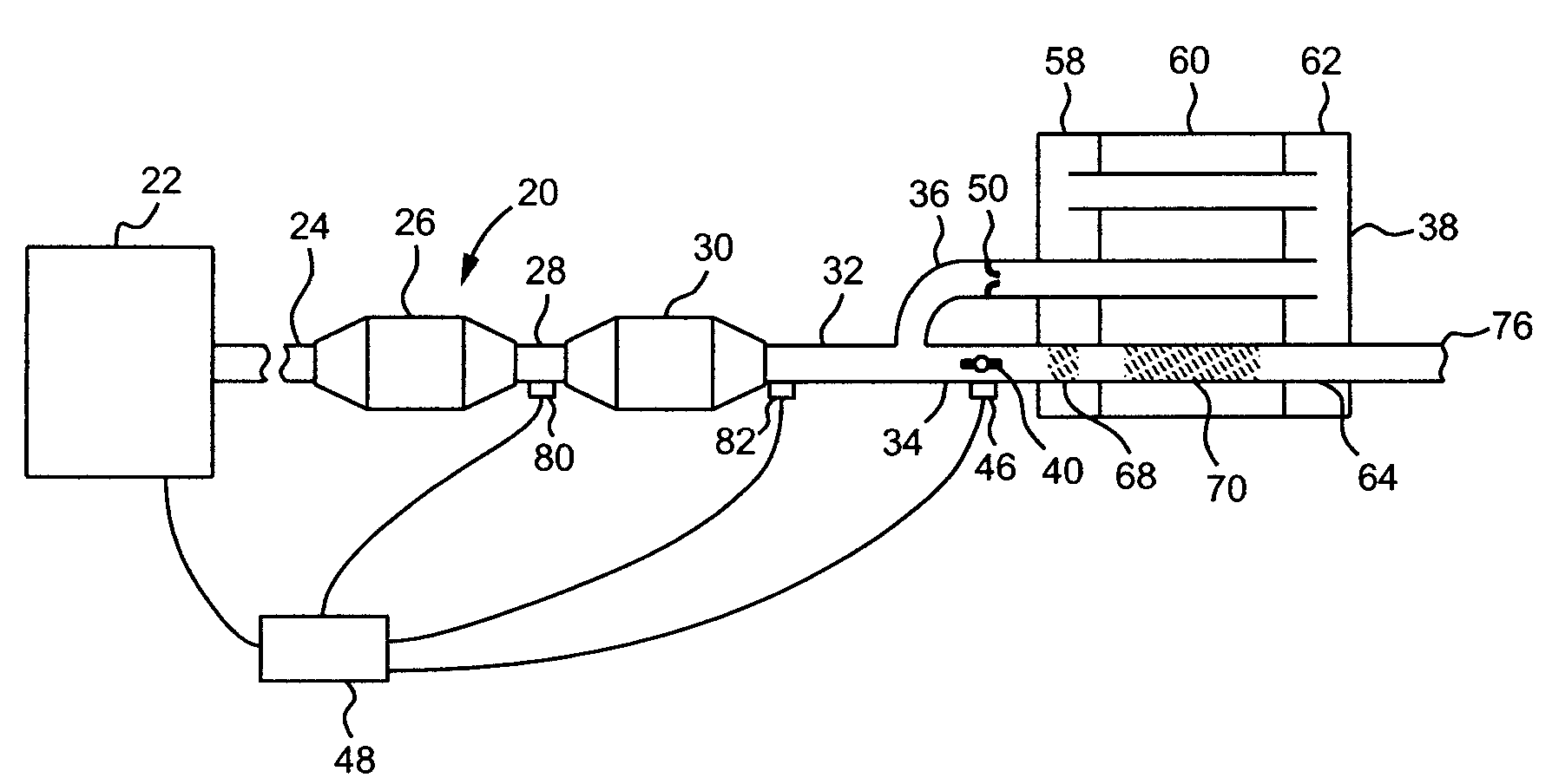
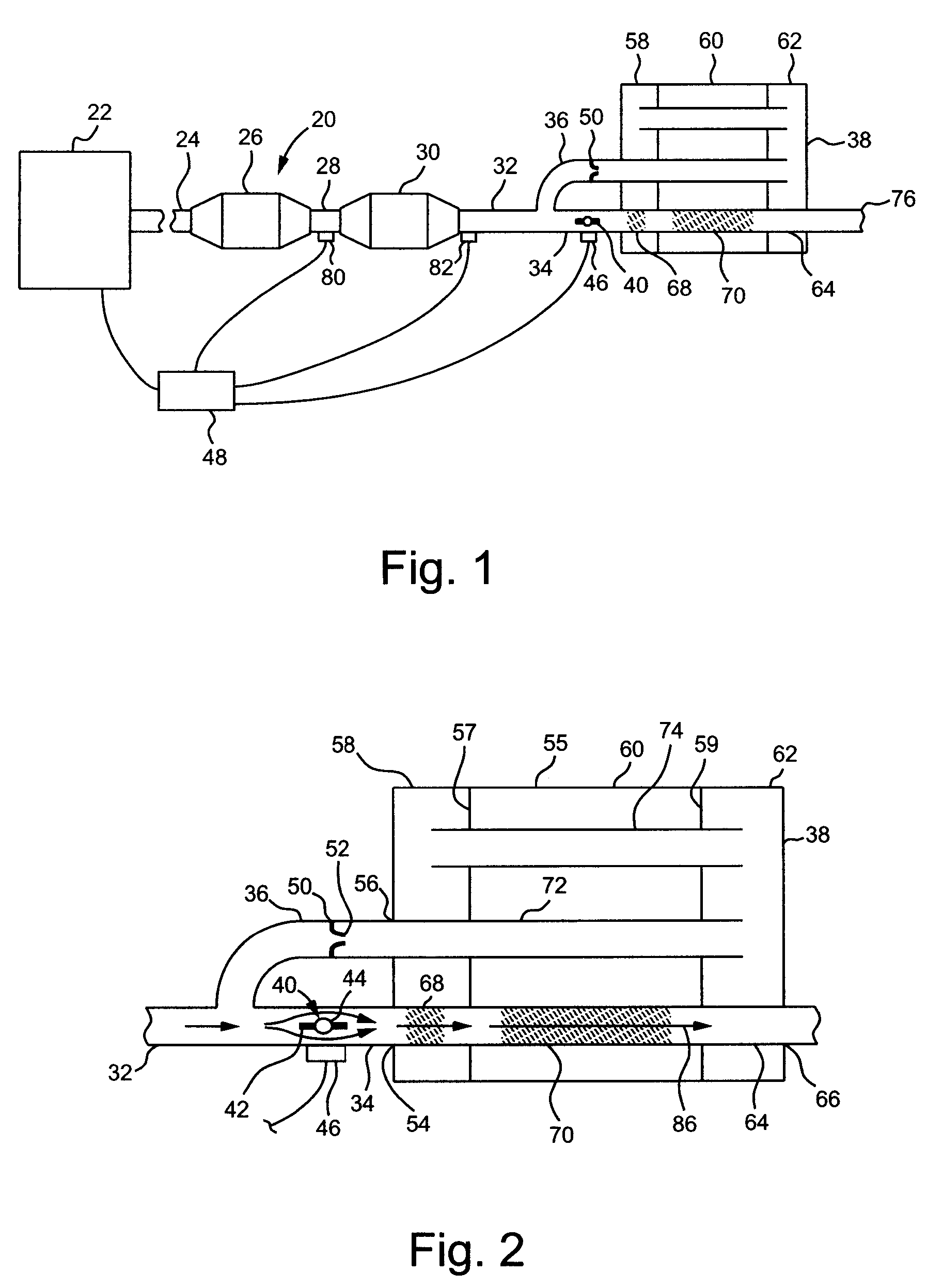
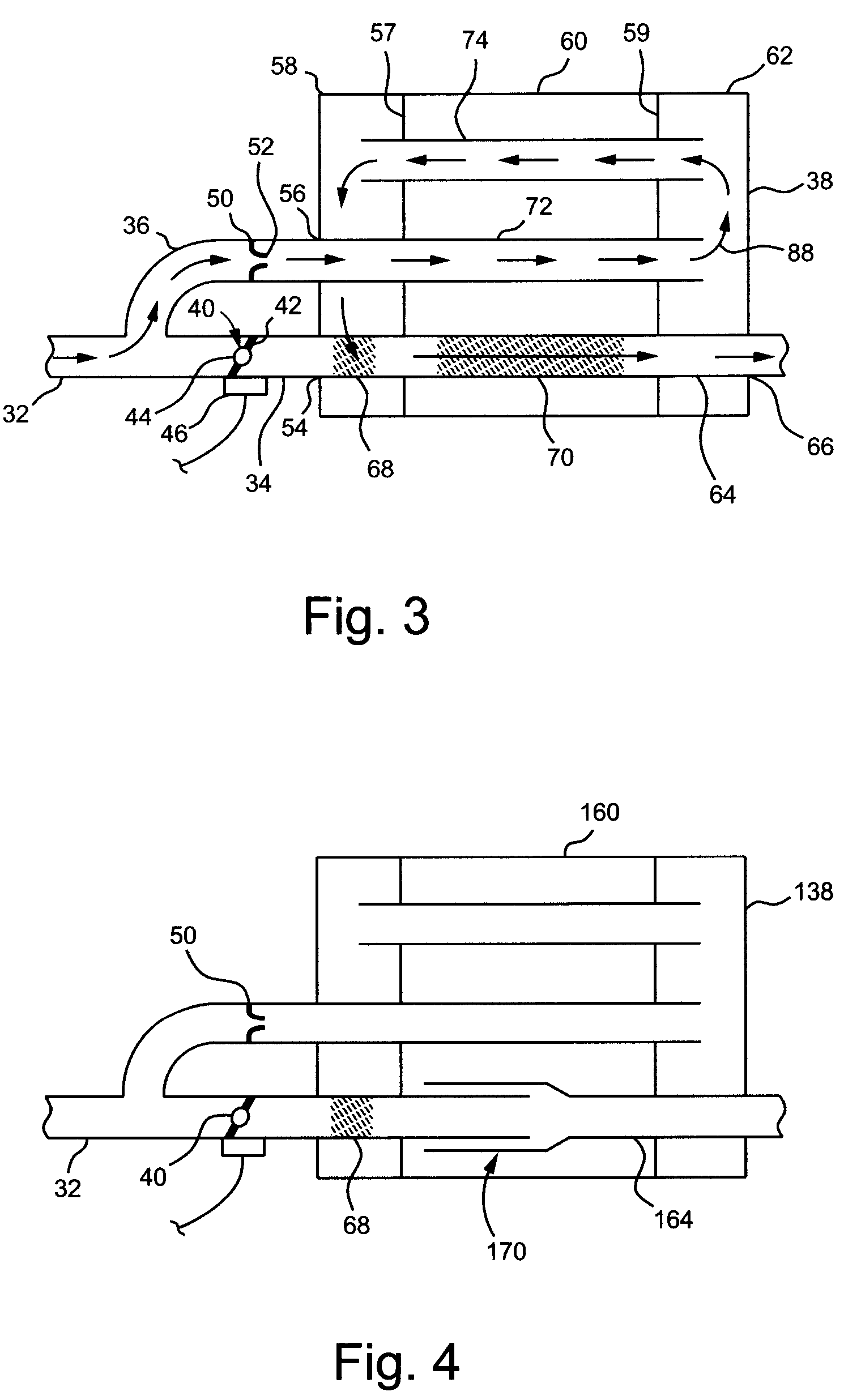
[0022]FIGS. 1-3 illustrate an exhaust system 20 that receives exhaust gasses from a diesel engine 22, treats the exhaust gasses, and directs them into the atmosphere away from the vehicle. More specifically, the exhaust system 20 includes an exhaust pipe 24—downstream of the engine 22—which directs the exhaust gases into a diesel oxidation converter 26 (also known as a diesel oxidation catalyst). The diesel oxidation converter 26 treats the exhaust gasses in order to reduce the amounts of certain constituents that will be emitted into the atmosphere. Such constituents may be, for example, carbon monoxide (CO) and unburned hydrocarbons (HC).

[0023]A first intermediate pipe 28 connects to the downstream end of the diesel oxidation converter 26 and directs the exhaust gasses into a diesel particulate filter 30 (also called a diesel particulate trap). The diesel particulate filter 30 is basically a filter for collecting (i.e., trapping) soot (also called diesel particulate matter) from t...


PUM


Abstract

The invention concerns diesel particulate filter regeneration in an exhaust system of a vehicle having a diesel engine. The particulate filter regeneration is selectively accomplished by actuating a particulate filter backpressure valve located downstream of the diesel particulate filter. Exhaust noise is attenuated for both normal driving and regeneration modes of operation by directing the exhaust flow through different flow paths in a muffler downstream of the diesel particulate filter.

Description

BACKGROUND OF INVENTION[0001]The present invention relates generally to an exhaust system in a vehicle having a diesel engine.[0002]Recent emissions regulations for vehicles employing diesel engines limit the amount of soot that the vehicles may emit. The soot is produced as a by-product of the combustion of the diesel fuel and is emitted with the vehicle exhaust. Diesel particulate filters (also called traps) added to the exhaust system limit the soot emissions sufficiently to meet the regulations.[0003]Diesel particulate filters work by collecting the soot while allowing the exhaust gasses to pass through. As the vehicle operates, then, the soot builds up in the filter. This soot needs to be periodically eliminated from the filter in order to assure that the filter does not become clogged. A clogged filter can potentially cause damage to itself or the engine.[0004]The particulate matter that builds up in the filter can be removed through a process called regeneration. Regeneration...

Claims


Application Information

Patent Timeline
Patent Type & Authority Patents(United States)
IPC IPC(8): F01N3/00
CPCF01N1/165F01N1/166F01N3/023F01N3/0235
Inventor MAHNKEN, BRIAN W.SANTURTUN, SANTIAGOPARK, JEFFREY M.
Owner GM GLOBAL TECH OPERATIONS LLC
Learn More