System and method for aligning sensors on a vehicle

a technology for aligning sensors and vehicles, applied in the direction of speed/acceleration/shock measurement devices, control devices, instruments, etc., can solve the problems of not being noticed by the operator, the sensor apertures would start to become misaligned, and the cost of the vehicle operator is high

Active Publication Date: 2008-03-04
AUTOBRILLIANCE LLC +1
View PDF16 Cites 129 Cited by
  • Summary
  • Abstract
  • Description
  • Claims
  • Application Information

AI Technical Summary

Problems solved by technology

This technique is not only costly, but would be require if a sensor aperture were repaired or replaced after production.
Also as the vehicle goes through normal wear and tear the sensor apertures would start to become misaligned and may not be noticed by the operator...

Method used


Image

  • System and method for aligning sensors on a vehicle
  • System and method for aligning sensors on a vehicle
  • System and method for aligning sensors on a vehicle

Examples


Embodiment Construction

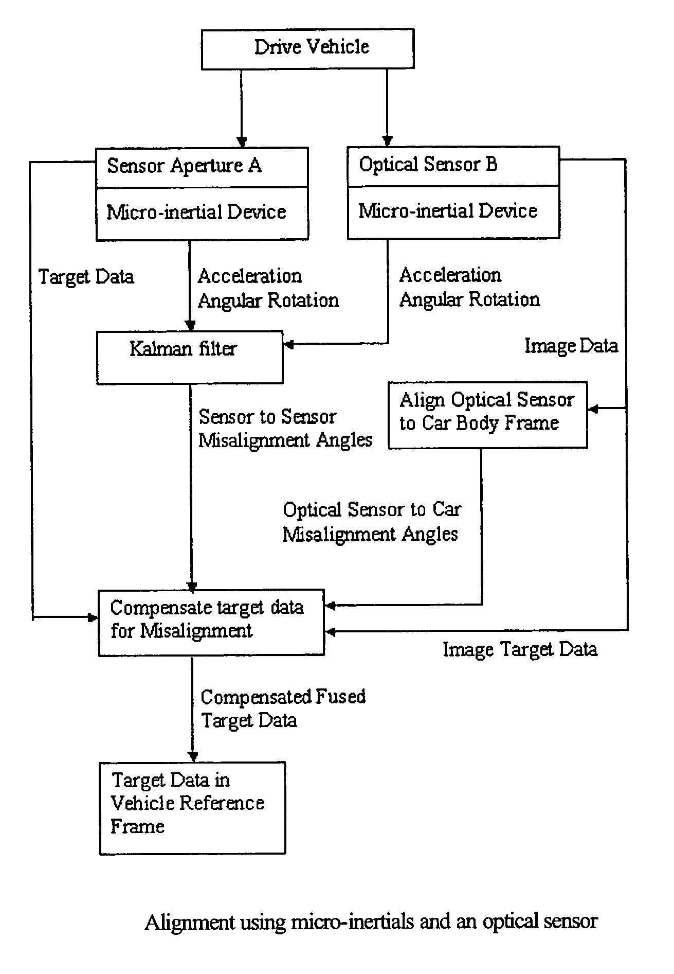
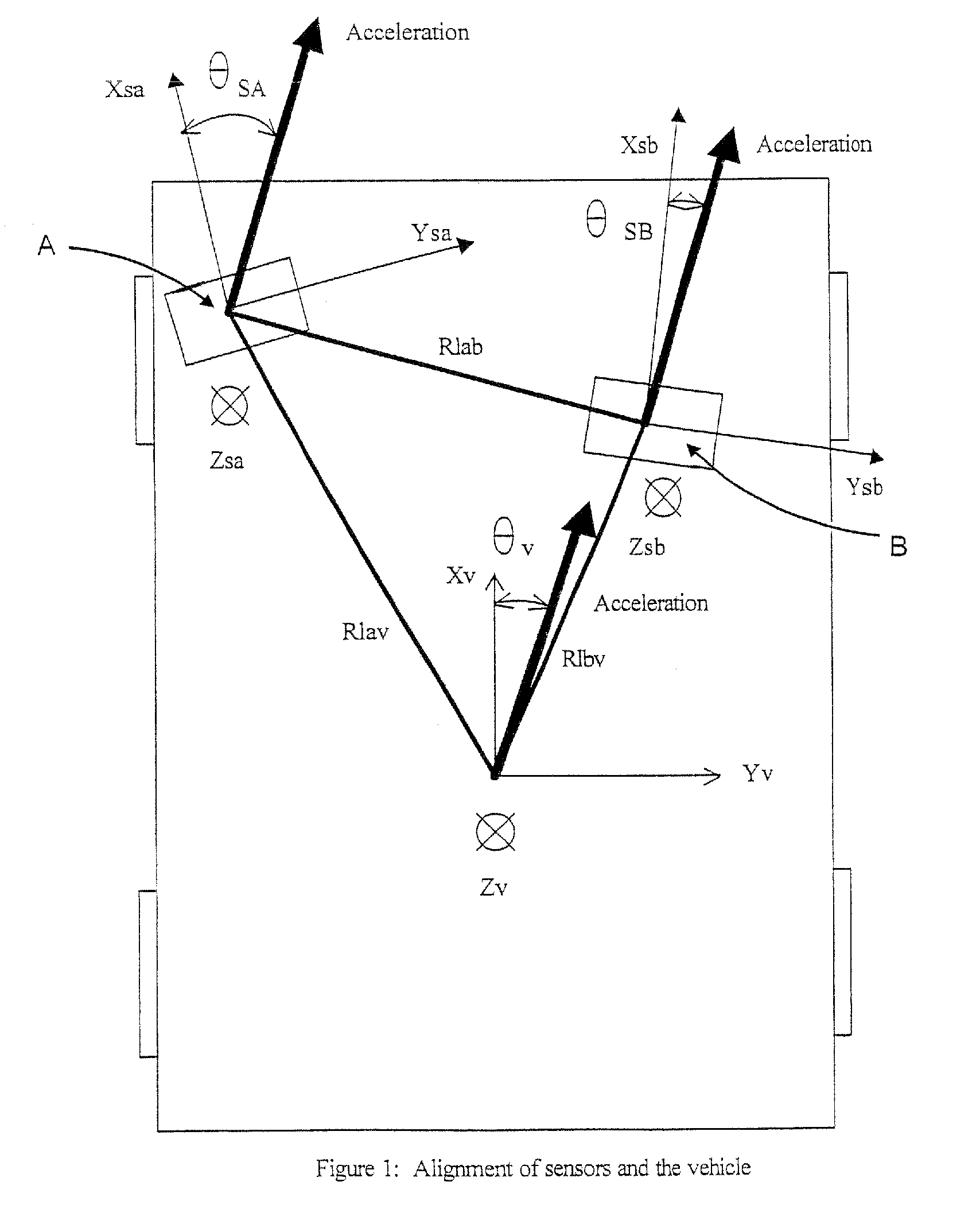
[0048]One method is to attach three axis accelerometers to each sensor and to the vehicle and use gravity and the acceleration of the vehicle, which will be sensed by the accelerometers, to align the sensor axes to each other and to the vehicle. Information from the vehicle that is available on the Car Area Network (CAN) bus will also be used to perform the calculation of the misalignment angles. FIG. 1 shows in two dimensions the relation between sensor aperture A frame, sensor aperture B frame and the vehicle body reference frame. There are two accelerometers that sense acceleration in the X and Y axes of the sensor apertures and vehicle. This problem can easily be expanded to three dimensions with another accelerometer located in the Z-axes of each sensor and vehicle.

[0049]In FIG. 1 the vehicle experiences a linear acceleration and this common acceleration is observed by the accelerometers located on sensor aperture A, sensor aperture B and the vehicle body. The accelerometers th...


PUM


Abstract

A vehicle sensor system consisting of video, radar, ultrasonic or laser sensors, oriented to obtain a 360 degree view around the vehicle for the purpose of developing a situation or scene awareness. The sensors may or may not have overlapping field of views, or support the same applications, but data will be shared by all. Orientation of the sensor to the vehicle body coordinates is critical in order to accurately assess threat and respond. This system describes methods based on measuring force and rotation on each sensor and computing a dynamic alignment to first each other, then second to the vehicle.

Description

RELATED FILINGS[0001]This application incorporates by reference U.S. Pat. No. 6,629,033, Issued Sep. 30, 2003 Titled—OPEN COMMUNICATION SYSTEM FOR REAL-TIME MULTIPROCESSOR APPLICATIONS, U.S. Pat. No. 6,771,208, Issued Aug. 3, 2004 Titled—MULTI SENSOR SYSTEM, and U.S. patent application Ser. No. 09 / 841,915, filed Apr. 24, 2001 entitled: METHOD AND APPARATUS FOR DYNAMIC CONFIGURATION OF MULTIPROCESSOR SYSTEMREFERENCES CITED[0002]U.S. Patent Documents[0003]U.S. Pat. No. 5,245,909 May 7, 1990; Title: Automatic Sensor Alignment; Inventors: Corrigan; John D. (Bridgeton, Mo.); Simmons, Jr.; Dennis E. (St. Louis, Mo.); Berg; Robert L. (St. Louis, Mo.); Assignee: McDonnell Douglas Corporation (MD)[0004]U.S. Pat. No. 6,202,027 Mar. 13, 2001; Title: Automatic curve sensor calibration method for an automotive CW / ICC system; Automatic curve sensor calibration method for an automotive CW / ICC system[0005]U.S. Pat. No. 5,031,330 Jul. 16, 1991; Title: Electronic Boresight; Inventors: Stuart; Kenneth...

Claims


Application Information

Patent Timeline
IPC IPC(8): G01P21/00
CPCB60W40/11B60W40/114B60W50/045B60W40/112B60W40/107B60W40/109B60W2050/0085B60W2050/0013G01P15/02
Inventor PRESTON, DAN ALANOLMSTEAD, DAVID N.
Owner AUTOBRILLIANCE LLC
Why Eureka
Try Eureka