Needle threading machine

a needle threading machine and needle thread technology, applied in the field of needle threading machines, can solve the problems of loss of work time, inconvenient, unavoidable need, etc., and achieve the effect of increasing the durability of the thread catcher and reducing the damage of the thread

Inactive Publication Date: 2008-03-04
INBRO
View PDF12 Cites 5 Cited by
  • Summary
  • Abstract
  • Description
  • Claims
  • Application Information

AI Technical Summary

Benefits of technology

[0006]Accordingly, it is an aspect of the present invention to provide a needle threading machine capable of not only reducing damage on a thread but also increasing the durability of a thread catcher.

Problems solved by technology

In a sewing machine, an automatic embroidering machine or the like, there is unavoidably needed a needle threading work that passes a thread through an eye of a needle provided in a lower part of a head stem in order to change an upper thread.
Such a needle threading work takes much time and is inconvenient.
Particularly, the thread is frequently changed in the case of the automatic embroidering machine that uses various colored threads, thereby causing the loss of work time.
Therefore, friction between the thread passing through the eye of the needle and the hook causes damage on the thread.
Also, because the hook is repeatedly deformed, the durability of the hook is decreased and the hook is damaged.

Method used


Image

  • Needle threading machine
  • Needle threading machine
  • Needle threading machine

Examples


first embodiment

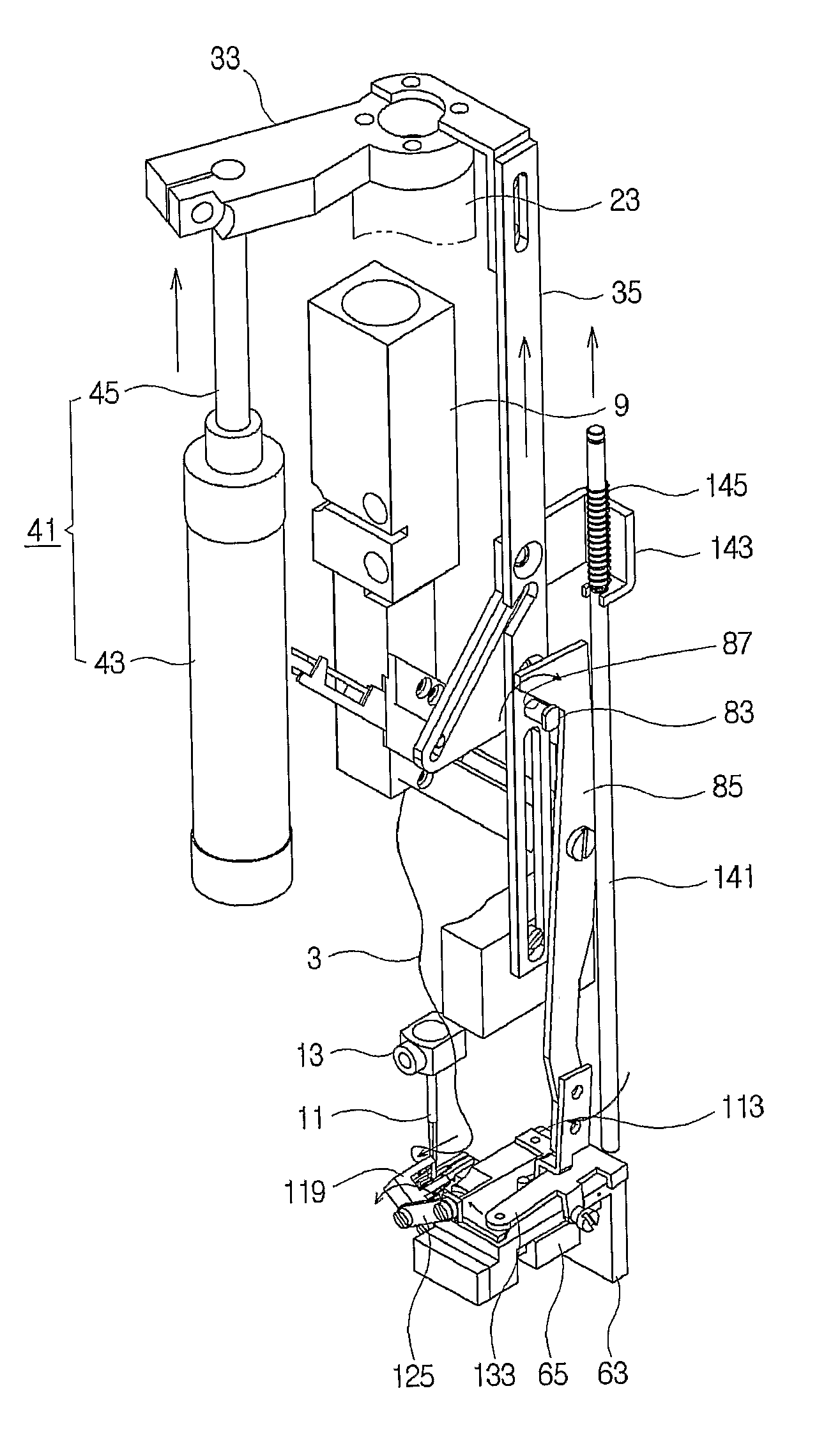
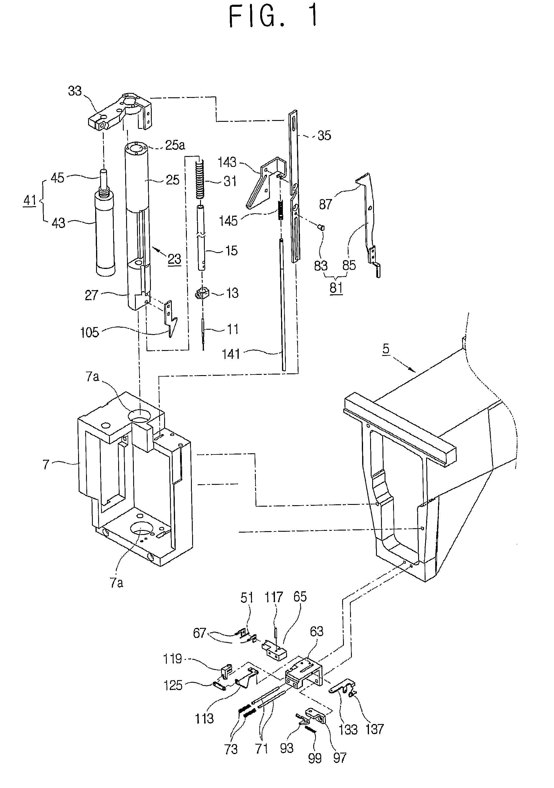
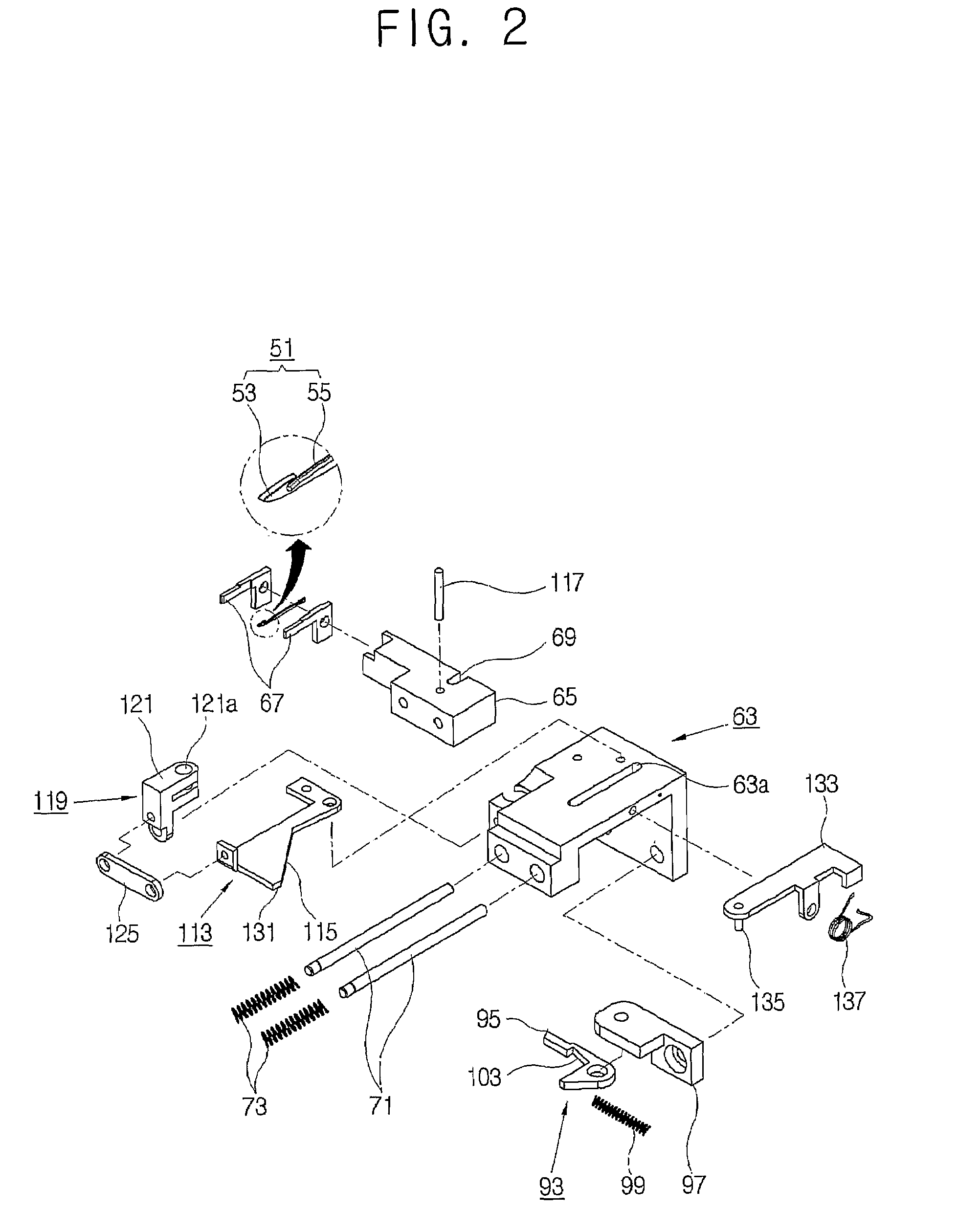
[0027]As shown in FIGS. 1 and 2, a needle threading machine 1 according to the present invention includes a needle 11 threaded with a thread supplied from a thread supplying unit 9 along a predetermined thread guiding path (not shown).

[0028]The needle 11 reciprocates within a predetermined sewing work section passing through a needle plate (not shown), and is mounted to an end of a needle bar 15 by a needle holder 13.

[0029]The needle bar 15 is shaped like a tube-body, and controllably connected to a needle bar driver (not shown) reciprocating within a predetermined section, by a clutch (not shown). Thus, the needle bar 15 is connected to the needle bar driver through the clutch, so that the needle 11 mounted to the end of the needle bar 15 reciprocates within the sewing work section by the reciprocating operation of the needle bar driver, thereby performing a sewing operation.

[0030]Meanwhile, the needle threading machine 1 according to an embodiment of the present invention includes...

second embodiment

[0090]In the second embodiment, an arm driving pin 181 is used as the arm driver. The arm driving pin 181 protrudes from a first surface of the arm 171, thereby being in contact with and spaced from the side of the needle bar bush 23. As the arm driving pin 181 moves being in contact with and spaced from the side of the needle bar bush 23, the rotation of the arm 171 is controlled.

[0091]In the needle threading machine 1′ with this configuration according to the second embodiment of the present invention, operations of transporting the thread 3 held in the hook 53 of the thread catcher 51 along the hook supporter 55 are as follows.

[0092]As shown in FIGS. 12A and 12B, when the needle bar 15 is lifted down from the needle threading section to the sewing work section in the state that the hook 53 of the thread catcher 51 holds the thread 3 and is returned from the eye 11a of the needle 11, the side of the needle bar bush 23 is in contact with the arm driving pin 181, so that the arm 171...


PUM


Abstract

The present invention relates to a needle threading machine of putting a thread through an eye of a needle provided in a sewing machine, the needle threading machine comprising a thread catcher comprising a hook to hook the thread, and a hook supporter extended from the hook and supporting the hook; a thread catcher driver driving the thread catcher to reciprocate allowing the hook to be inserted in and return from the eye of the needle; and a thread transporting unit transporting the thread caught in the hook away from the hook after the hook is returned from the eye of the needle. Thus, the present invention provides a needle threading machine capable of not only reducing damage on a thread but also increasing the durability of a thread catcher.

Description

FIELD OF THE INVENTION[0001]The present invention relates to a needle threading machine for a sewing machine.BACKGROUND ART[0002]In a sewing machine, an automatic embroidering machine or the like, there is unavoidably needed a needle threading work that passes a thread through an eye of a needle provided in a lower part of a head stem in order to change an upper thread.[0003]Such a needle threading work takes much time and is inconvenient. Particularly, the thread is frequently changed in the case of the automatic embroidering machine that uses various colored threads, thereby causing the loss of work time.[0004]Accordingly, there has been disclosed a needle threading machine in Korean Patent Application No. 2000-52077. In this needle threading machine, a hook is provided in the end of a thread catcher and holds the thread. Further, the thread catcher is reciprocated between the needle and a predetermined position spaced from the needle, so that the hook passes through the eye of th...

Claims


Application Information

Patent Timeline
Patent Type & Authority Patents(United States)
IPC IPC(8): D05B87/02D05B55/00
CPCD05B87/02
Inventor PARK, HAM-KYUPARK, IL-GYU
Owner INBRO
Why Eureka
Try Eureka