Test strip dispenser

a dispenser and test strip technology, applied in the field of containers and vials, can solve the problems of electro-mechanical devices adding cost to the kit, the risk of spilling the entire contents of the vial, etc., and achieves the effect of simple use and low manufacturing cos

Active Publication Date: 2008-03-04
NOVA BIOMEDICAL
View PDF35 Cites 152 Cited by
  • Summary
  • Abstract
  • Description
  • Claims
  • Application Information

AI Technical Summary

Benefits of technology

[0008]It is an object of the present invention to provide a strip dispenser that is inexpensive to manufacture. It is another object of the present invention to provide a strip dispenser that is simple to use. It is a further object of the present invention to provide a strip dispenser that dispenses a test strip one at a time without the risk of spilling the contents of the strip dispenser. It is still another object of the present invention to provide a strip dispenser that uses a simple, structural arrangement of components to achieve the consistent dispensing of a test strip one at a time.
[0011]Strip vial component has a first vial portion, a second vial portion, a magazine receiving end, a closed end and the vial recess previously disclosed. The vial recess has a shoulder portion spaced from the closed end and positioned in the vial recess so that it is adjacent to and aligned with the open magazine top. The first vial portion is configured for slidably engaging the inner surface of the outer magazine casing. The first vial portion also incorporates an O-ring groove spaced from the magazine receiving end and in the outer surface of first vial portion. An O-ring placed within the O-ring groove provides controlled resistance to the slidability of the strip vial component in the outer magazine casing.
[0015]The combination and cooperation of the strip magazine, the magazine spring, the strip vial component and the cover provides a simple, manual way to dispense a single strip from a strip dispenser without exposing all of the strips stored within the strip magazine to the user or potential outside contaminants. The present invention works by simply pulling the strip magazine and the strip vial component away from each other until a first stop position is reached. In the process of reaching the first stop position, several actions concurrently occur internally within the strip dispenser. The strip ejection component moves away from the magazine volume and the top most strip of the stack of strips within the strip magazine is pushed by the biasing force of the magazine spring into an ejection position, i.e. into the strip ejection space or zone. The ejection position places the flat surface of the strip against the strip positioning surface of the vial recess and also places the strip in position for ejection out through the slit in the cover.
[0016]As the strip magazine and the strip vial component are moved towards each other to a closed position, the strip magazine engages a second stop surface. During this process, the strip ejection surface of the strip ejection component engages the end of the strip that is in the ejection position and pushes a portion of the strip out of the slit in the cover. The user can then withdraw the entire strip from the strip dispenser. Concurrently with the ejection of the strip, the strip ejection component slides over the surface of the next available strip in the strip stack, thus holding the strip stack in ready position for the next strip ejection procedure.

Problems solved by technology

There are, however, several disadvantages of the prior art.
The use of simply vials creates a risk of spilling the entire contents of the vial when one is extracting a single disposable and / or consumable.
In the case where the disposable / consumable is a test strip, the spilled test strips could get contaminated depending on where they were spilled and, if contaminated, would have to be discarded.
The more sophisticated, electro-mechanical devices add cost to the kit due to the addition of more complicated and more expensive parts used to eject and electrically connect a test strip for use.

Method used


Image

  • Test strip dispenser
  • Test strip dispenser
  • Test strip dispenser

Examples


Embodiment Construction

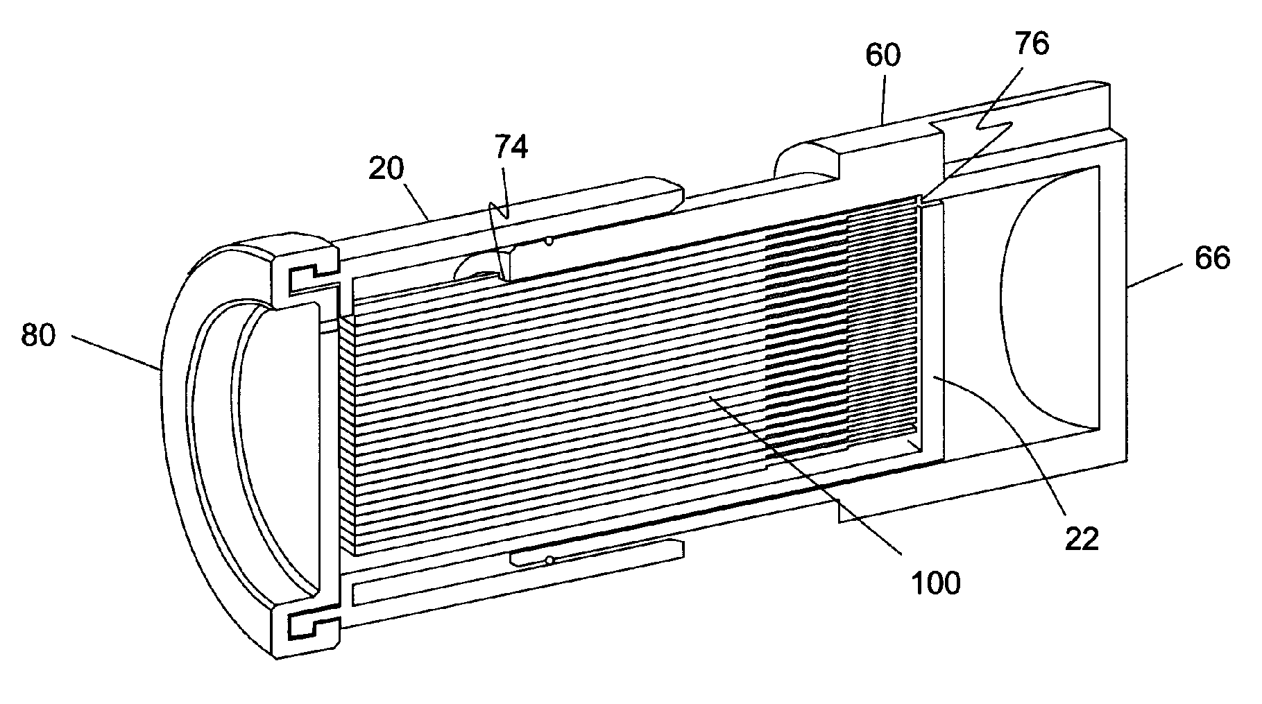
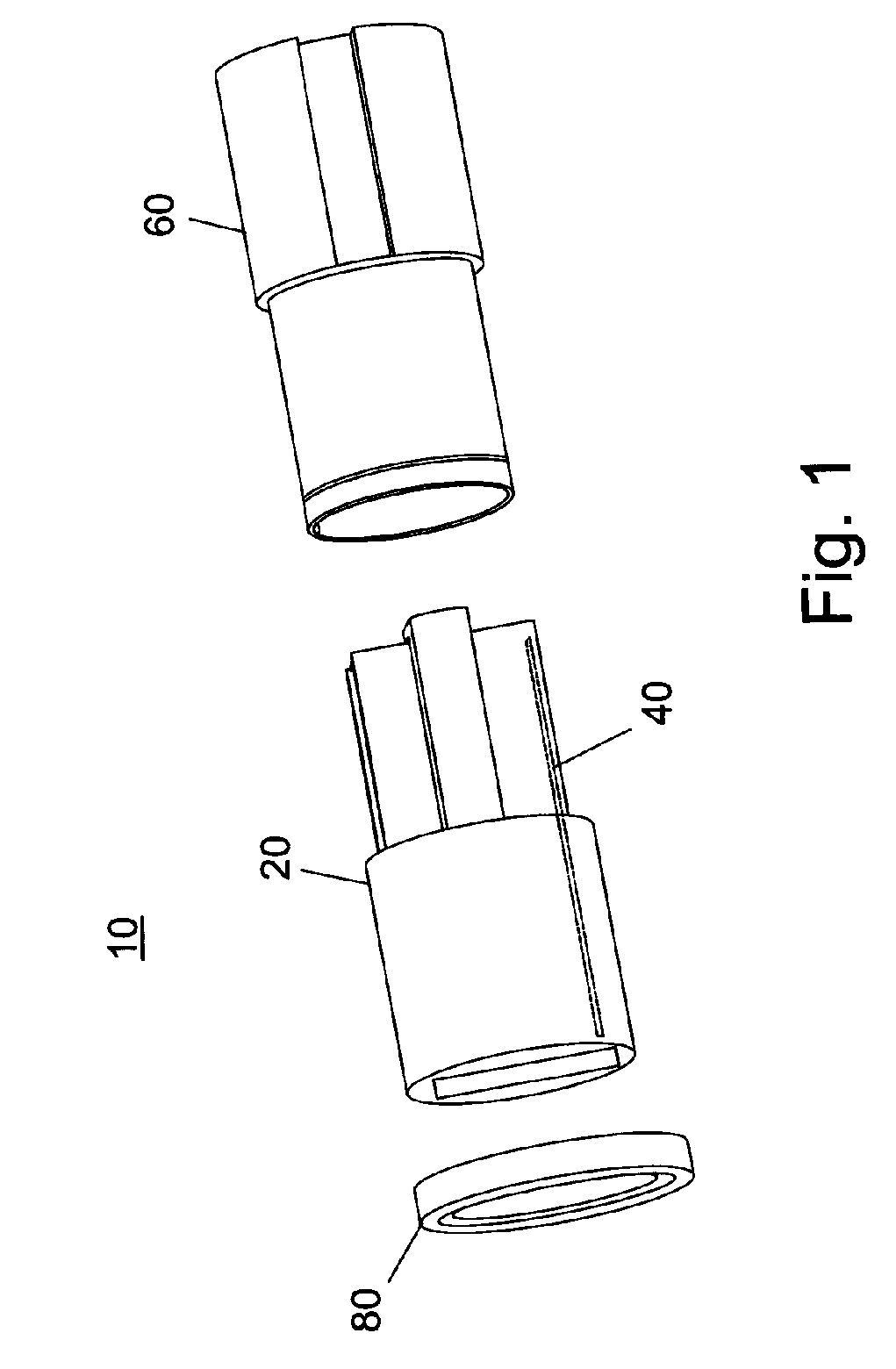
[0031]The preferred embodiment of the present invention is illustrated in FIGS. 1-12. FIG. 1 illustrates the test strip dispenser 10 of the present invention. Test strip dispenser 10 includes a strip magazine 20, a magazine spring 40, a strip vial component 60, and a cover 80. Strip magazine 20 and strip vial component 60 are preferably made of a polymer material such as a plastic. Magazine spring 40 may be made of plastic or metal, but is preferably made of metal for longer life.

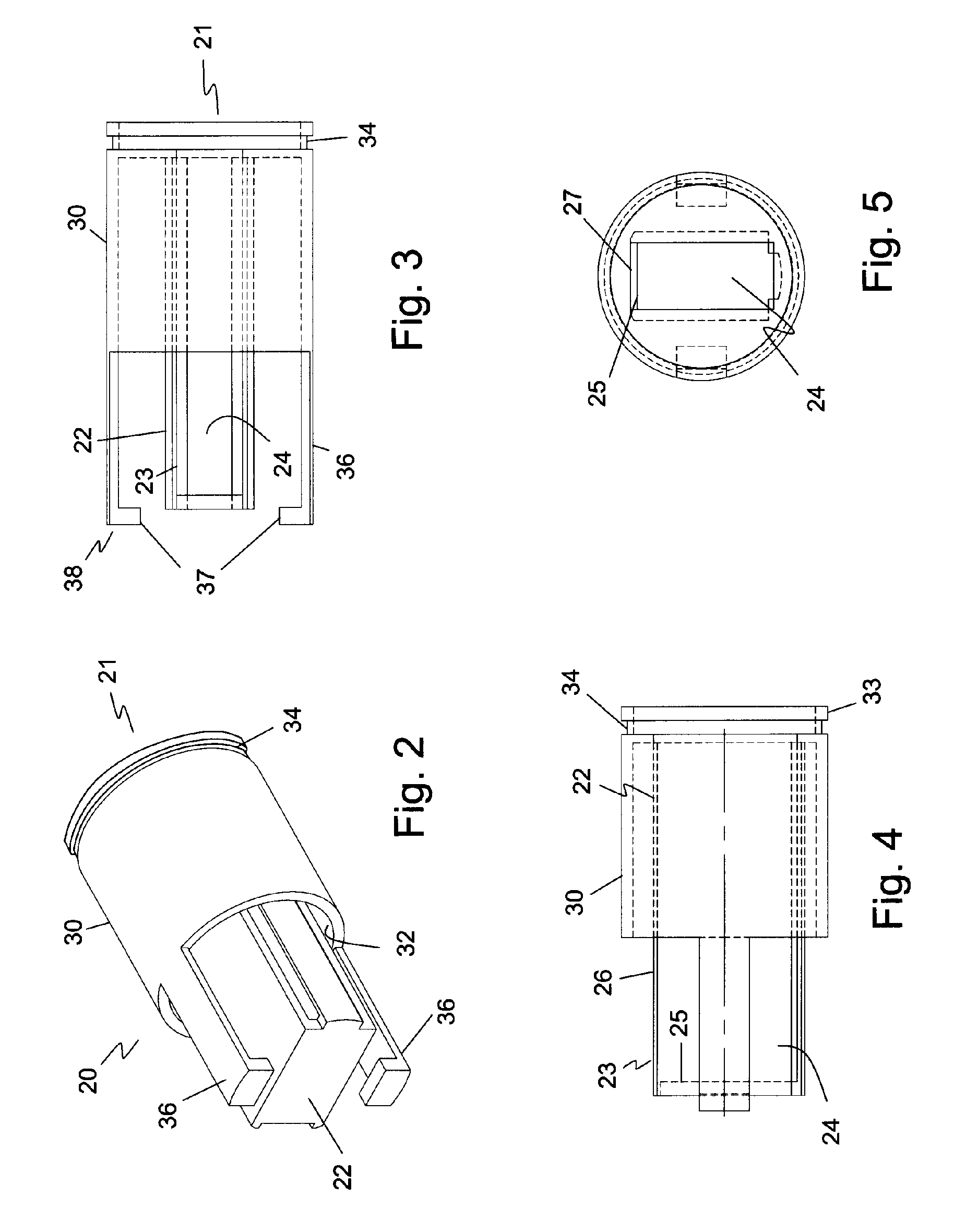
[0032]Turning now to FIG. 2, there is illustrated a perspective view of strip magazine 20. Strip magazine 20 includes a strip container portion 22, an outer magazine casing 30 and a magazine open end 21 (not shown). Outer magazine casing 30 surrounds the strip container portion 22 for a predefined distance along the strip container portion 22. An inner surface 32 of outer magazine casing 30 is spaced from outer surface of strip container portion 22.

[0033]Outer magazine casing 30 also includes a circumferent...


PUM


Abstract

A strip dispenser has a strip magazine, a magazine spring, a strip vial component, and a cover. The strip magazine has a magazine open end and an outer magazine casing surrounding the strip magazine adjacent the open end for a predefined distance along the strip magazine where the magazine has a magazine volume with an open magazine top. The magazine spring is contained within the strip magazine. The strip vial component has a magazine receiving end, a closed end and a vial recess for slidably receiving the strip magazine between a first position and a second position where the vial recess has a shoulder portion spaced from the closed end and adjacent to and aligned with the open magazine top. The cover encloses the magazine open end and has a slit spaced a predefined distance from an edge of the cover where the slit is in communication with the magazine volume and the open magazine top and in spatial alignment with the shoulder portion.

Description

BACKGROUND OF THE INVENTION[0001]1. Field of the Invention[0002]The present invention relates generally to containers and vials. Particularly, the present invention relates to test strip vials. More particularly, the present invention relates to test strip dispensers.[0003]2. Description of the Prior Art[0004]Over the years, various kits have been devised that include items known as disposables and / or consumables. The disposables and / or consumables are generally one component of a multi-component kit. These kits are typically used for qualitative testing or quantitative testing or both. For example, kits exist to test for the presence of particular chemical species in the air, smoke stacks, water, and the like. Other kits have been developed for testing the presence of biological species. Still other kits have been developed particularly for use in patient treatment. One example of such a medical test kit is a kit to test the glucose level in blood, particularly for use by diabetics...

Claims


Application Information

Patent Timeline
Patent Type & Authority Patents(United States)
IPC IPC(8): B65D83/00B01L3/00B65H1/08G07F11/16
CPCB65D83/0829
Inventor FOWLER, JAMESDAGGETT, ROBERT
Owner NOVA BIOMEDICAL
Why Eureka
Try Eureka