
Extendable vehicle steering shaft

a vehicle steering and extension technology, applied in mechanical devices, couplings, transportation and packaging, etc., can solve the problems of increasing manufacturing costs, incompatibility of cost reduction, and excessive assembly time, so as to reduce the backlash in the peripheral direction, reduce the assembling time, and reduce the manufacturing cost

Active Publication Date: 2008-03-04
NSK LTD
View PDF21 Cites 8 Cited by
  • Summary
  • Abstract
  • Description
  • Claims
  • Application Information

AI Technical Summary

Benefits of technology

The present invention provides a telescopic shaft for vehicle steering that can achieve stable slide load, transmit torque in a high-rigidity state, and increase lifetime by reducing both assembly time and surface pressure. This is achieved by using cylindrical torque transmission members that gradually decrease in diameter towards the end portions in the axial direction. The cylindrical members are preferably subjected to crowning to further reduce backlash and surface pressure while restraining slide resistance. Additionally, the torque transmission members can be worked in a tapered configuration to apply gentle surface pressure towards the central portion from the end portion. Overall, the invention improves the performance and durability of the telescopic shaft for vehicle steering.

Problems solved by technology

EP1078843A1, however, each set of torque transmission members (the cylindrical members) are constructed of the plurality of needle rollers arranged side by side in the axial direction, and therefore, the assembly is complicated enough to take an excessive period of assembling time.
This inevitably involves machining the grooved portions and induces a rise in manufacturing cost.
Hence, enhanced performance (which reduces the backlash in the peripheral direction while restraining the slide resistance low) and a decrease in cost can not be compatible.
Moreover, if the accuracy of straightness of each of the male shaft and the female shaft is not enhanced, a high surface pressure might occur in the vicinity of an end face of the needle roller when transmitting the torque.

Method used


Image

  • Extendable vehicle steering shaft
  • Extendable vehicle steering shaft
  • Extendable vehicle steering shaft

Examples


Embodiment Construction

[0023]A telescopic shaft for vehicle steering according to an embodiment of the present invention will hereinafter be described with reference to the drawings.

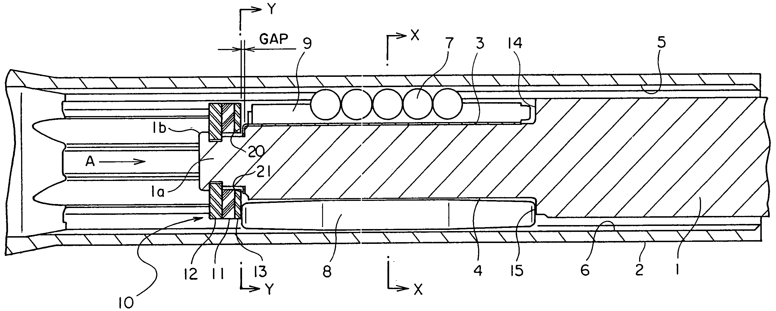
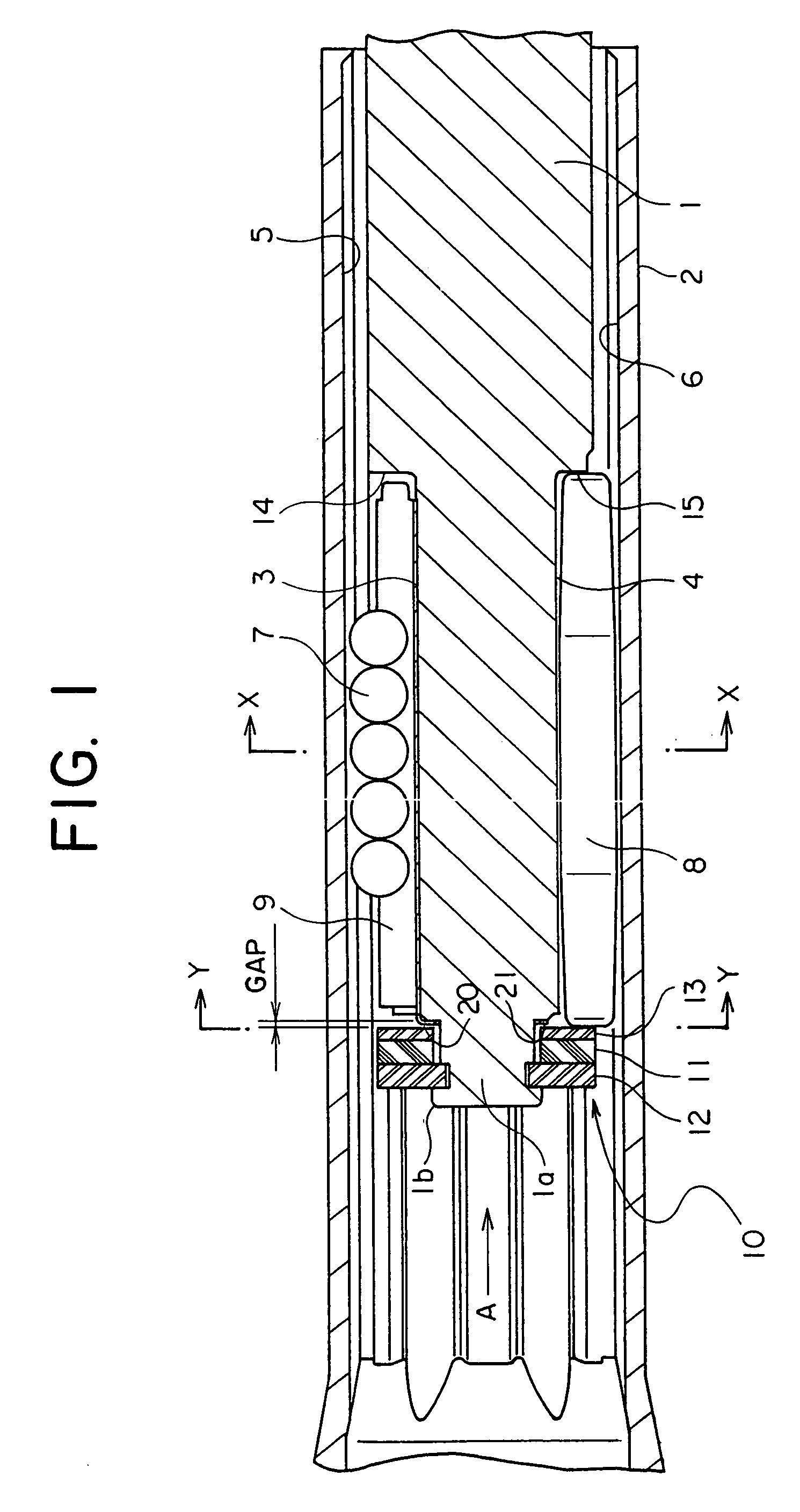
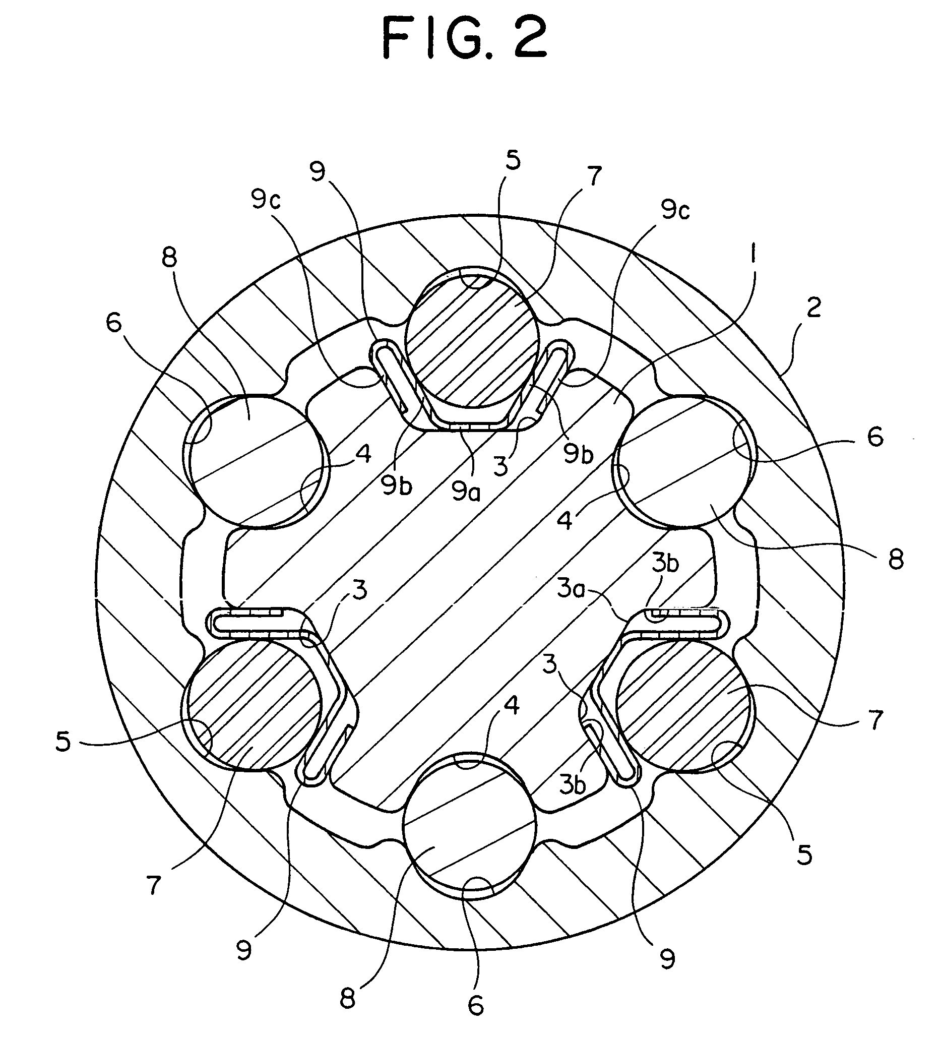
[0024]FIG. 1 is a longitudinal sectional view showing the telescopic shaft for the vehicle steering according to the embodiment of the present invention. FIG. 2 is a cross-sectional view taken along the line X-X in FIG. 1.

[0025]As illustrated in FIG. 1, the telescopic shaft for the vehicle steering (which will hereinafter simply be termed the telescopic shaft) is constructed of a male shaft 1 and a female shaft 2 that are so fitted as to be mutually incapable of rotating but mutually slidable.

[0026]As shown in FIG. 2, an outer peripheral surface of the male shaft 1 is formed with three lines of grooves 3 equally disposed at an interval of 120 degrees in a peripheral direction and extending in an axial direction. Each groove 3, as apparent in FIG. 2, in its cross-sectional configuration, has a flat bottom portion 3a at the cent...


PUM


Abstract

In a telescopic shaft for vehicle steering, assembled in a steering shaft of a vehicle and including a male shaft and a female shaft so fitted as to be mutually incapable of rotating but mutually slidable, at least one set of torque transmission members are disposed in at least one set of accommodating portions formed in an outer peripheral surface of the male shaft and in an inner peripheral surface of the female shaft, and at least the one set of torque transmission members are cylindrical members that gradually decrease in their diameters toward end portions in an axial direction.

Description

TECHNICAL FIELD[0001]The present invention relates to a telescopic shaft for vehicle steering, capable of actualizing a stable slide load and transmitting torque in a high-rigidity state by surely preventing backlash.BACKGROUND ARTS[0002]FIG. 7 shows a general type of steering mechanism of an automobile. In FIG. 7, the symbols a and b represent telescopic shafts. The telescopic shaft a is constructed by spline-fitting a male shaft and a female shaft to each other. This type of telescopic shaft is, however, required to have performance that absorbs an axis-directional displacement occurred when the automobile travels but transmits neither the displacement nor vibrations onto a steering wheel. This performance is required generally in such a structure that a vehicle body takes a sub-frame structure, a portion c for fixing an upper portion of the steering mechanism and a frame e to which a steering rack d is fixed are different units, and the frame e and the steering rack d are fixed b...

Claims


Application Information

Patent Timeline
Patent Type & Authority Patents(United States)
IPC IPC(8): F16C3/035B62D1/16B62D1/18B62D1/185B62D1/20B62D7/22F16D3/06
CPCB62D1/185B62D1/20B62D7/224F16C3/035F16D3/06F16D3/065F16C29/007F16C29/04F16C29/123F16C2326/24
Inventor YAMADA, YASUHISA
Owner NSK LTD
Learn More