Textile prosthesis

a technology of prosthesis and woven fabric, applied in the field oftextile prosthesis, can solve the problems of distorted weave, distorted woven structure, and change of the fixation point on the fabric, and achieve the effect of less structural distortion

Inactive Publication Date: 2008-03-04
ELLIS DEV +1
View PDF13 Cites 68 Cited by
  • Summary
  • Abstract
  • Description
  • Claims
  • Application Information

AI Technical Summary

Benefits of technology

[0008]A general aim of the present invention is to provide a textile prosthesis, in particular but not excl...

Problems solved by technology

With a conventional woven textile, if a screw is pushed through the interstices of the woven structure, any load that is applied to the textile will be concentrated at one part of the weave structure, often on a single weft yarn causing the loaded yarn to move within the woven structure causing the weave to become...

Method used


Image

  • Textile prosthesis
  • Textile prosthesis
  • Textile prosthesis

Examples


first embodiment

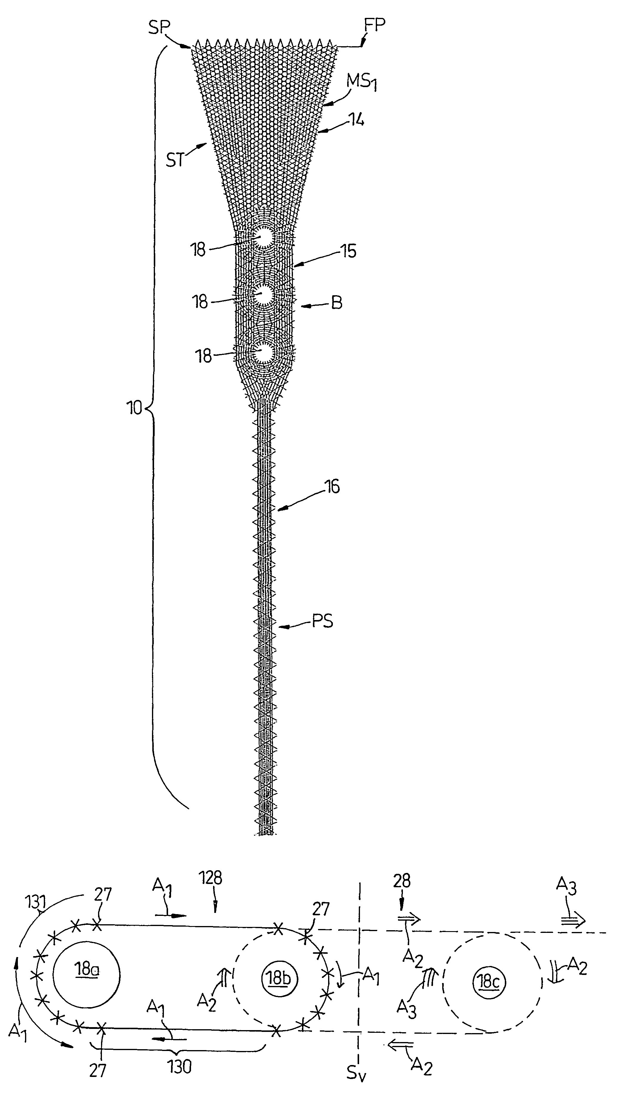
[0080]Described below, by way of example, are various specific embodiments. In FIG. 8 there is shown a first embodiment which is a surgical implant suitable for the repair of the shoulder of a human being, intended to reinforce the natural, but damaged tissue.

[0081]The implant comprises a body 10 which is generally planar and includes a first discrete body portion 14, a second discrete body portion 15 and a third discrete body portion 16.

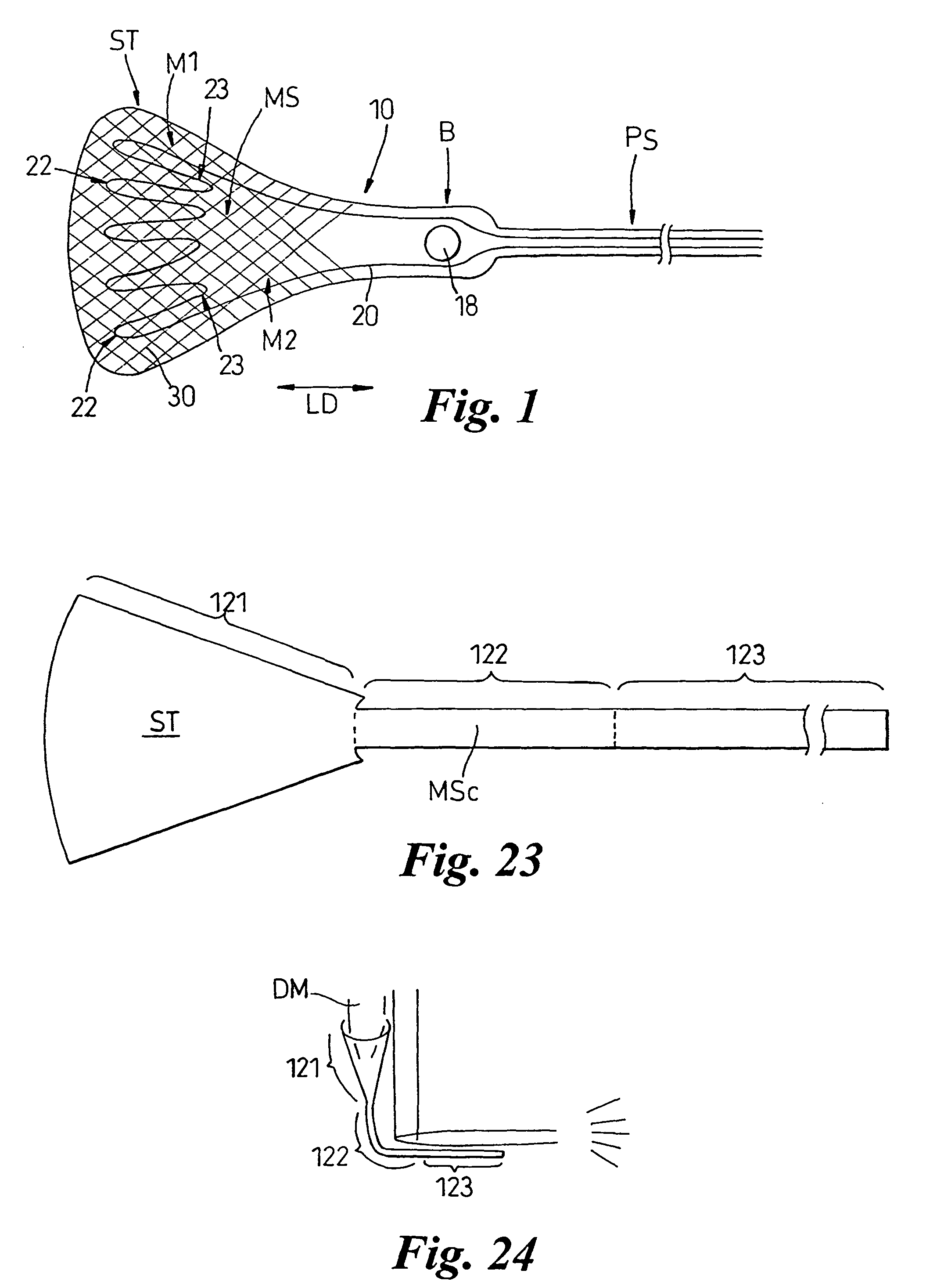
[0082]The first body portion 14 defines an anchorage body portion ST, comprising a mesh-like structure MS1 formed from binding yarns 30 in which load bearing yarns 20 are trapped. The anchorage portion ST is intended to be sutured to the natural tendon material forming the rotator cuff of the shoulder.

[0083]The body portion 15 defines an anchorage body portion B and preferably includes three apertures 18 each of which enable a bone screw to pass therethrough for securing the body portion 15 to the humeral bone. Three apertures 18 are provided in ord...

embodiment 80

[0117]The embodiment 80 illustrated in FIG. 16 is a multiple ligament reinforcement prosthesis. Prosthesis 80 includes three fan shaped anchorage body portions ST1, ST2, ST3 defined by body portions 81, 82 and 83 which are joined together by a connecting body portion 84.

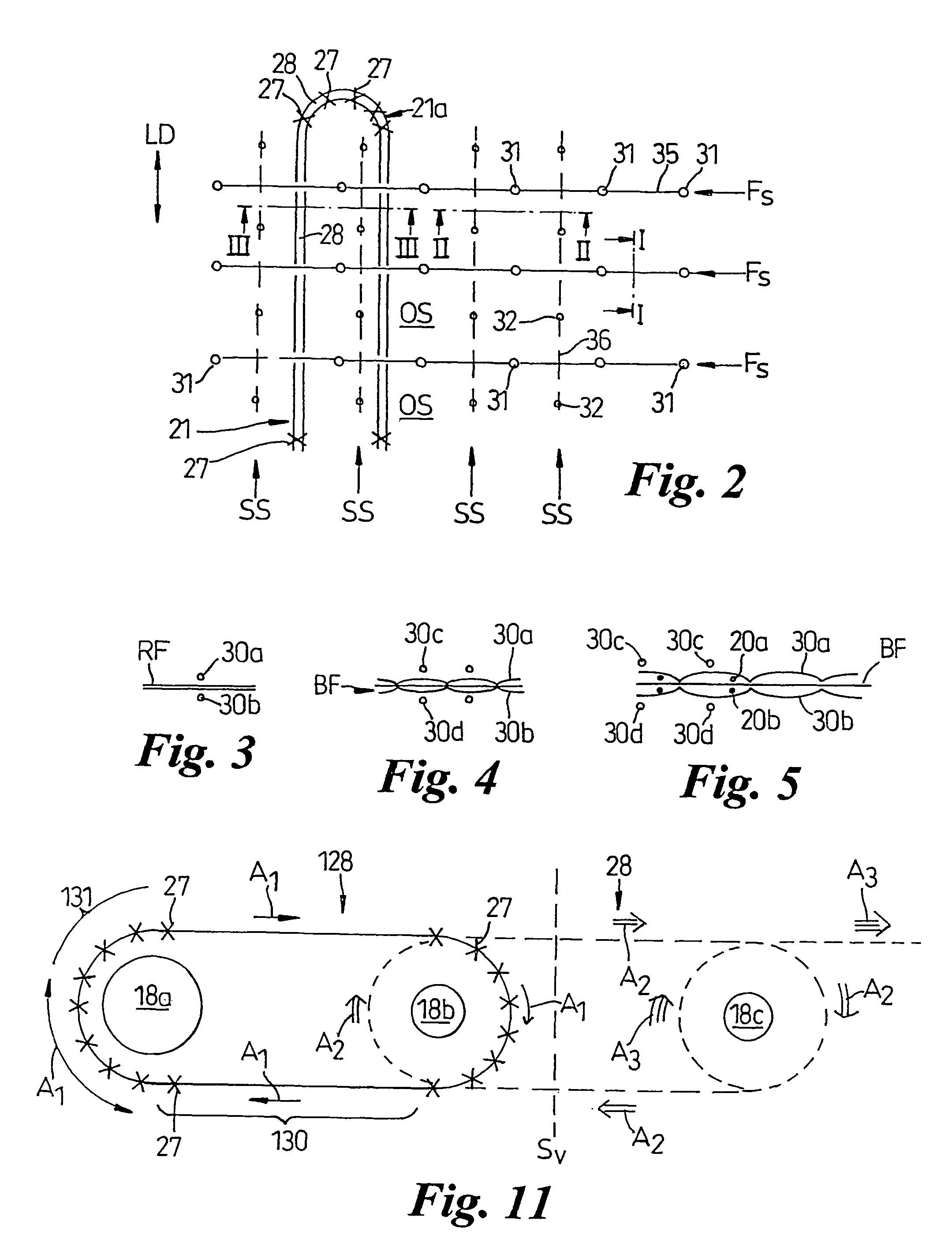
[0118]The body portions 81, 82 and 83 are of a similar structure to body portions 61, 62, 63 described above with the exception that the reinforcement yarn 66 is replaced by a reinforcement yarn 86 which is placed by a succession of stitches 87 which define arcuate zig-zag formations 88 which serve to prevent the fabric fraying after a surgeon has cut inbetween the formations 88. Preferably the yarn 86 has a contrasting colour to the other yarns in order to give the surgeon an easily recognisable guide for cutting.

[0119]Preferably the prosthesis 80 includes two arm portions 90 which form pulling ribbons PS connected to body portion 84. Load bearing yarns 20 extend continuously through both arm portions 90 and the con...

embodiment 100

[0127]Embodiment 100 illustrated in FIG. 21 comprises a body 12 having two discrete anchorage body portions B1, B2 defined by two body portions 101, 102 which are connected to one another only by tensile load bearing yarn length portions 21.

[0128]The yarn 20 is secured within body portions 101, 102 by star formations 40 and binding yarns 30 which preferably form a mesh-like structure MS. The yarn lengths 21 cross over from right to left and left to right as they extend between the body portions 101, 102. By suitable placement using the embroidery machine, each length portion 21 is of a predetermined length so that all length portions 21 have the same tensile load applied thereto when body portions 101, 102 are pulled part. This has the advantage that there will not be a cascade failure of one yarn length 21 breaking after another once a first one of the lengths 21 has broken.


PUM


Abstract

A textile prosthesis comprising a unitary body of predetermined shape having structural integrity, the body including at least one anchorage body portion for attachment to an anatomical body part, the body being composed of a combination of binding yarns and tensile load bearing filaments, the binding yarns being located at least in the or in each of said anchorage body portions and being interconnected to one another by sewn stitches, the tensile load bearing filaments being located inbetween said stitches so as to be constrained to extend through said unitary body along predetermined pathways extending in one or more predetermined directions so as to render the body resistance to stretch when a tensile load is applied in said one or more predetermined directions.

Description

FIELD OF THE INVENTION[0001]The present invention relates in particular, but not exclusively, to a textile prosthesis and a method of producing a textile prosthesis.[0002]The prosthesis may be used to regenerate an external fleshy body part such as an ear or may be a surgical implant.BACKGROUND OF THE INVENTION[0003]In the design of textile surgical implants, it is often desirable to apply a tensile load to the textile structure. For example, in orthopaedic applications the textile implant may be used to replace a damaged ligament. Ligaments join bones to bones and during movement of the body, a load is applied to the ligaments. To anchor the replacement ligament in place, it may be convenient or desirable to use a screw fixation device to anchor the textile implant to the bone so that the load may be properly transferred across the joint.[0004]With a conventional woven textile, if a screw is pushed through the interstices of the woven structure, any load that is applied to the text...

Claims


Application Information

Patent Timeline
IPC IPC(8): A61F2/02A61F2/08A61B17/00A61L27/00A61B17/70A61F2/18
CPCA61B17/7022A61B17/7055A61B17/7059A61F2/08A61B17/8085A61B2017/00004A61B2017/00867A61F2002/183A61F2220/0075A61F2/02
Inventor ELLIS, JULIANBUTCHER, PETERMCLEOD, ALAN
Owner ELLIS DEV
Why Eureka
Try Eureka