Optical switches and switching methods

a technology of optical switches and switching methods, applied in the field of input devices, can solve the problems of affecting the collection of magnetic imaging data, introducing noise, and subject not being able to operate the device with both hands, or comfortably or stably rest, etc., and achieve the effect of eliminating the need for filters and reducing signal nois

Inactive Publication Date: 2008-03-04
MIND INST THE
View PDF6 Cites 20 Cited by
  • Summary
  • Abstract
  • Description
  • Claims
  • Application Information

AI Technical Summary

Benefits of technology

[0023]A further advantage of the present invention is that no metal parts are required to be in the magnet room, thus greatly reducing signal noise and eliminating the need for filters.

Problems solved by technology

Metallic components act as antennas and thus introduce noise, which must be filtered out using, for example, radio frequency (RF) filters.
However these devices have a number of disadvantages.
This is disadvantageous because for numerous magnetic imaging applications, the subject is not able to operate the device with both hands, or comfortably or stably rest his or her hand on a horizontal surface.
The subject must frequently reposition his or her fingers, thus interfering with the magnetic imaging data collected.
In addition, many such existing devices require electronics, such as an opto-electric converter, to be situated within the magnet room, thus inducing noise in the system and requiring costly filters.
Finally, these devices typically use plastic membrane-type switches, which are prone to failure.

Method used


Image

  • Optical switches and switching methods
  • Optical switches and switching methods
  • Optical switches and switching methods

Examples


Embodiment Construction

Best Modes for Carrying Out the Invention

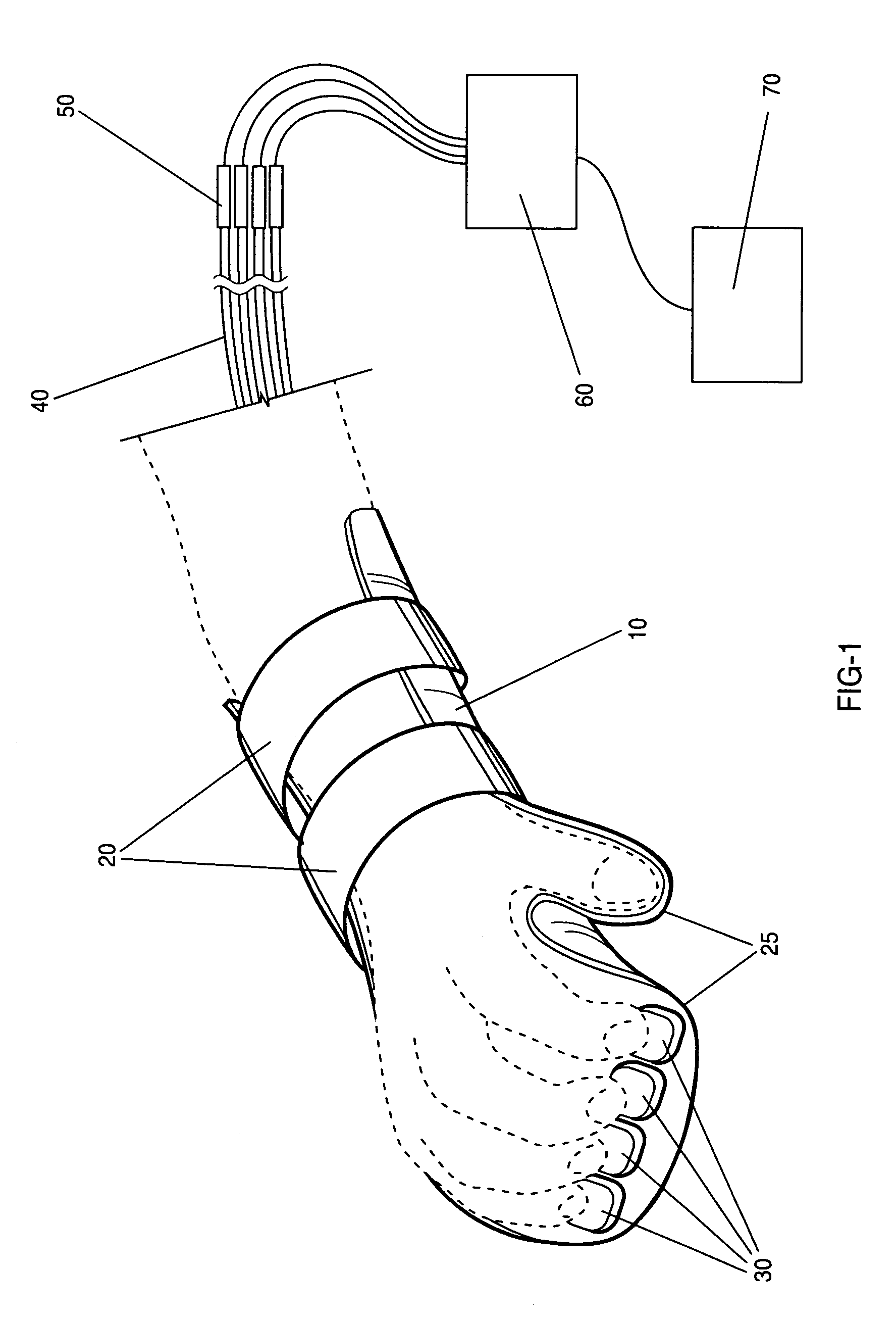
[0029]The present invention is a preferably nonmetallic input device for use in magnetic imaging applications, or any magnetic field system where switching or response detection within the magnetic field is required, which keeps a subject's fingers aligned with the switches of the device. The present invention is further a robust nonmetallic optical switch, and switching methods, for use with the input device. The switches of the present invention may alternatively comprise metallic parts.

[0030]As used throughout the specification and claims, “attach” means any method for removably attaching two objects, including but not limited to using a strap, tie, belt, adhesive, adhesive pad, adhesive patch, cuff, clamp, and the like.

[0031]As used throughout the specification and claims, “splint” means any device for at least partially immobilizing, or at least partially restricting the movement of, a portion of the body, including but not limited to ca...


PUM


Abstract

A device and method for collecting subject responses, particularly during magnetic imaging experiments and testing using a method such as functional MRI. The device comprises a non-metallic input device which is coupled via fiber optic cables to a computer or other data collection device. One or more optical switches transmit the subject's responses. The input device keeps the subject's fingers comfortably aligned with the switches by partially immobilizing the forearm, wrist, and / or hand of the subject. Also a robust nonmetallic switch, particularly for use with the input device and methods for optical switching.

Description

CROSS-REFERENCE TO RELATED APPLICATIONS[0001]This application is a continuation-in-part application of U.S. patent application Ser. No. 10 / 933,644, entitled “Nonmetallic Input Device for Magnetic Imaging and Other Magnetic Field Applications”, filed on Sep. 3, 2004, now U.S. Pat. No. 7,039,266, and the specification and claims thereof are incorporated herein by reference.FEDERALLY SPONSORED RESEARCH OR DEVELOPMENT[0002]The U.S. government has a paid-up license in this invention and the right in limited circumstances to require the patent owner to license others on reasonable terms as provided for by the terms of Contract No. DE-FG02-99ER62764 awarded by the U.S. Department of Energy.BACKGROUND OF THE INVENTION[0003]1. Field of the Invention (Technical Field)[0004]The present invention relates to an input device, which is preferably nonmetallic, and optical switches and switching methods therefore. An embodiment of the present invention is useful for transmitting reactions from a sub...

Claims


Application Information

Patent Timeline
Patent Type & Authority Patents(United States)
IPC IPC(8): G02B6/26
CPCG01R33/283G02B6/3574G02B6/353G02B6/3552
Inventor DOTY, MICHAEL
Owner MIND INST THE
Why Eureka
Try Eureka