Pressing plunger mechanism for a glassware forming machine

a technology of glassware forming machine and plunger mechanism, which is applied in the direction of press blowing machine, glass making apparatus, glass shaping apparatus, etc., can solve the problems of high construction cost, large space occupation, and inability to precisely control the movement of the pressure medium driv

Inactive Publication Date: 2008-03-11
HEYE INT
View PDF20 Cites 3 Cited by
  • Summary
  • Abstract
  • Description
  • Claims
  • Application Information

AI Technical Summary

Benefits of technology

[0019]The supply and telescopic pipes are protected against mechanical damage and against tipping with respect to each other by disposing them between the guide rods.

Problems solved by technology

This construction is expensive and takes up a large amount of space in the glassware forming machine.
However, precise movement control with a pressure medium drive is barely possible or is only possible at great expense.

Method used


Image

  • Pressing plunger mechanism for a glassware forming machine
  • Pressing plunger mechanism for a glassware forming machine
  • Pressing plunger mechanism for a glassware forming machine

Examples


Embodiment Construction

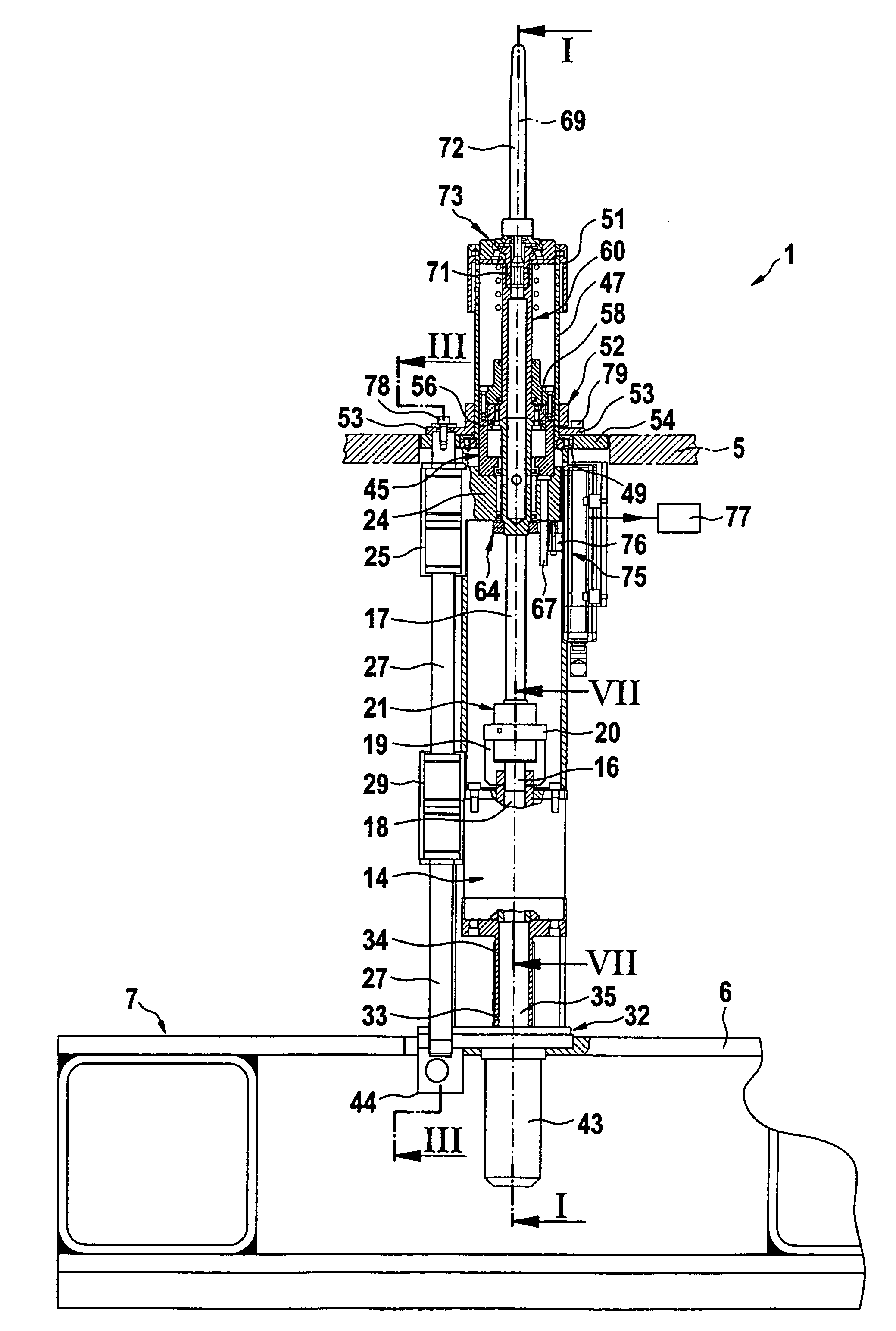
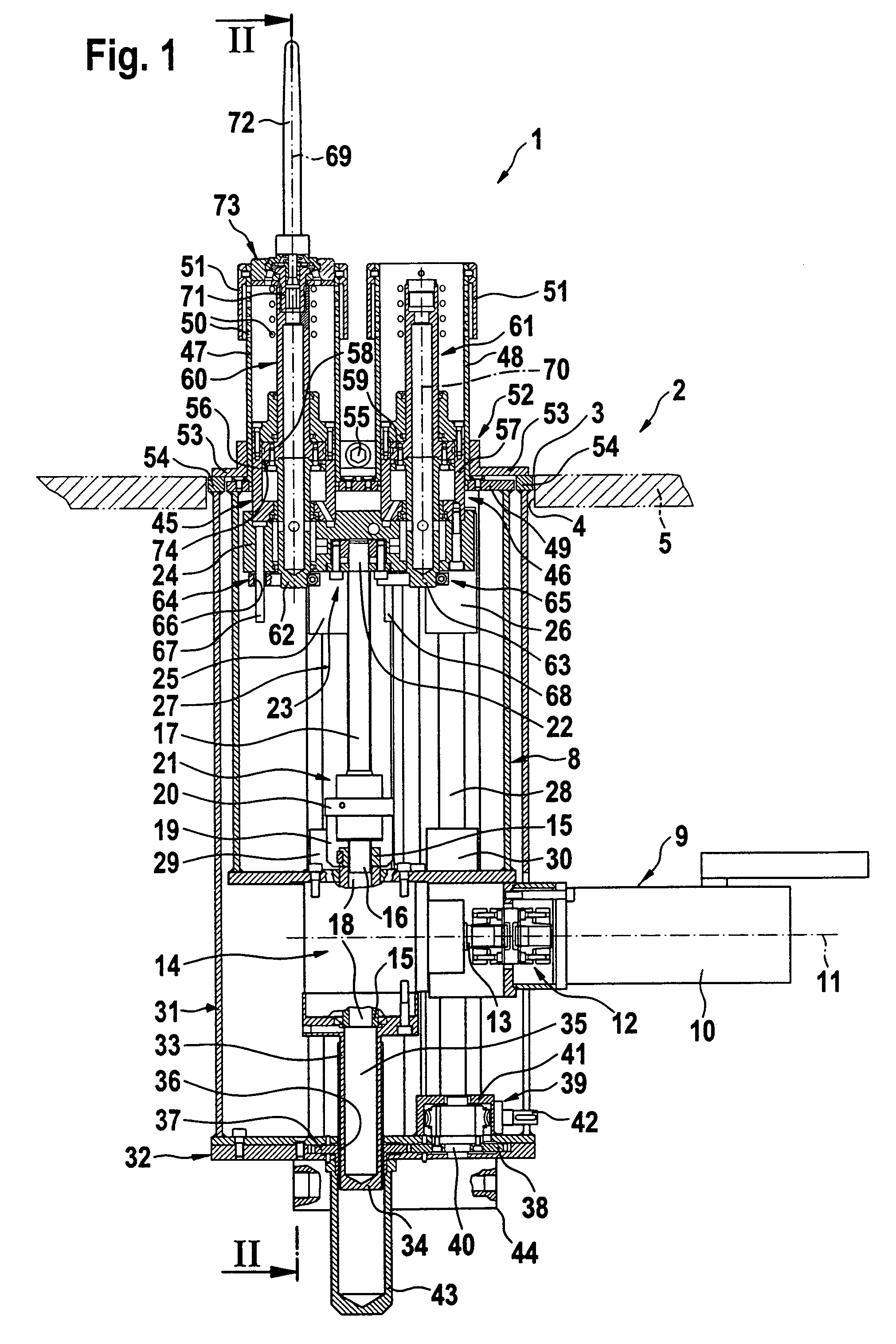
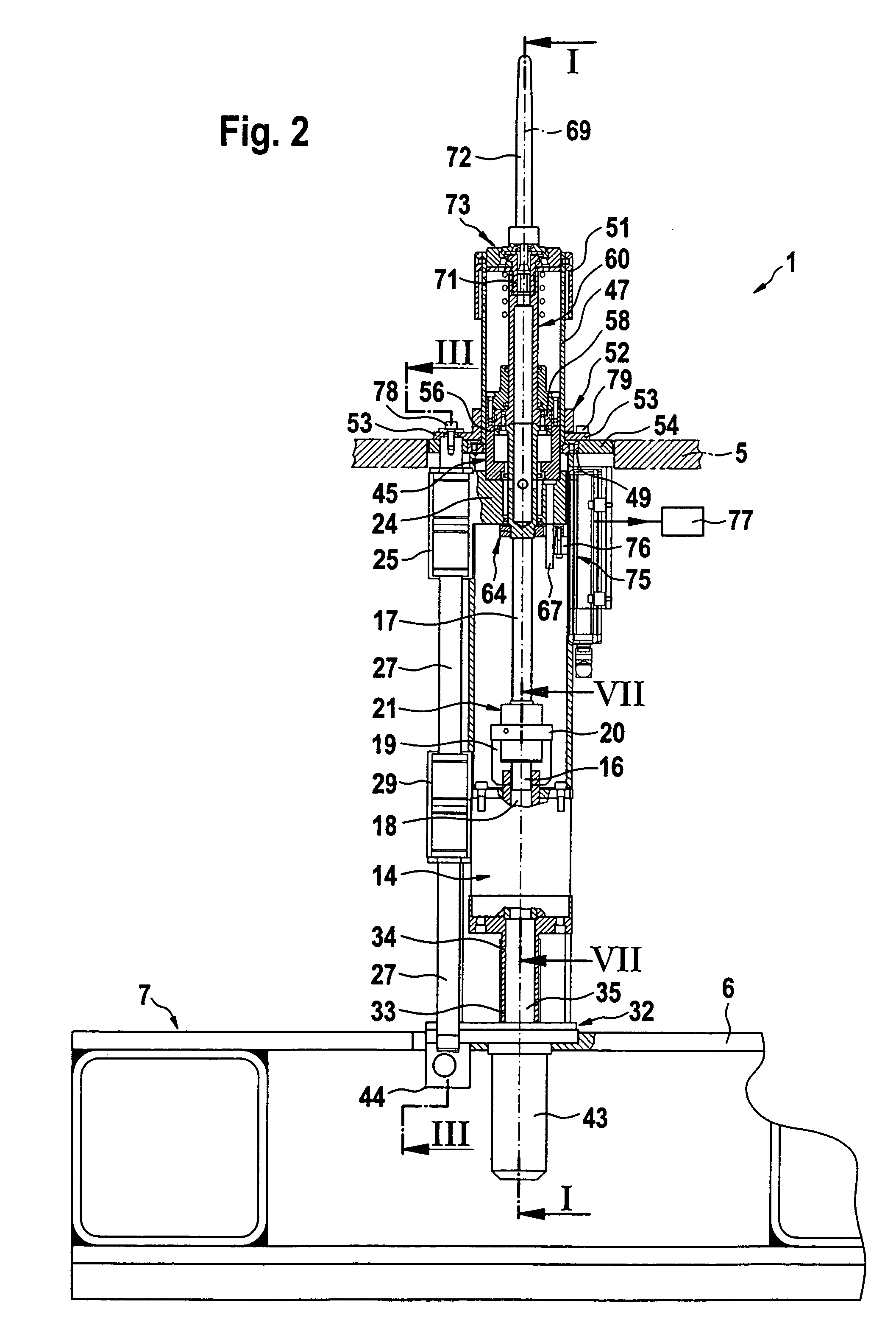
[0028]FIG. 1 shows a pressing plunger mechanism 1 of a glassware forming machine 2, this can be, for example, a section of an I.S. glassware forming machine. The glassware forming machine 2 operates in the illustrated exemplified embodiment in so-called double gob operation, wherein in each case two glass vessels are produced at the same time.

[0029]The pressing plunger mechanism 1 is inserted with a sealing gap 3 into an orifice 4 in an upper plate 5 of the glassware forming machine 2. In accordance with FIG. 2 the pressing plunger mechanism 1 is screwed at the bottom to a head plate 6 of a machine bed 7.

[0030]In accordance with FIG. 1 the pressing plunger mechanism 1 has a first housing 8 which supports a first drive 9. The first drive 9 has an electric servo motor 10 with a horizontal longitudinal axis 11, which is connected to an input shaft 13 of an angular gear 14 via a play-free elastic coupling 12.

[0031]A driven shaft 15 of the angular gear 14 has a space 18 receiving a free ...


PUM

PropertyMeasurementUnit
lengthaaaaaaaaaa
inner diameteraaaaaaaaaa
displacementaaaaaaaaaa

Abstract

A pressing plunger mechanism for a glassware forming machine has at least one pressing plunger which in normal operation can be moved axially in a reciprocating manner together with a pressing plunger receiver between an inoperative position and a pressing position. A piston rod of a piston is fastened to each pressing plunger receiver, which piston can be displaced in a cylinder of a pressing plunger holder. The pressing plunger holder can be moved axially in a reciprocating manner by a first drive and is connected in a non-rotatable manner to a threaded spindle. A nut which can be rotationally driven by the first drive is engaged with the threaded spindle and is coupled to a driven shaft of an angular gear. An input shaft of the angular gear can be rotationally driven by an electric servo motor of the first drive.

Description

FIELD OF THE INVENTION[0001]The invention relates to a pressing plunger mechanism for a glassware forming machine.BACKGROUND OF THE INVENTION[0002]In the case of a known pressing plunger mechanism as disclosed in DE 30 40 762 C2 of the applicant the pressing plunger holders are driven by a crank gear (column 6, lines 22 and 23). This construction is expensive and takes up a large amount of space in the glassware forming machine.[0003]An alternative type of drive for the pressing plunger holders is known from U.S. Pat. No. 5,411,564. These pressing plungers are accordingly each moved axially in a reciprocating manner by a piston-cylinder unit between a pressing and an inoperative position. This pressure medium drive is supported by a first housing which is disposed so that it can be adjusted with respect to a machine frame in parallel with the longitudinal direction of the pressing plungers by means of a further drive formed as a spindle drive. This latter-named spindle drive is form...

Claims


Application Information

Patent Timeline
Patent Type & Authority Patents(United States)
IPC IPC(8): C03B11/06C03B9/193C03B9/40
CPCC03B9/1936C03B9/1938C03B9/40C03B9/403C03B9/406C03B9/41
Inventor BOGERT, HERMANNKASSNER, WALDEMARMONDEN, NORBERT
Owner HEYE INT
Why Eureka
Try Eureka