Rim mounted pressure monitoring system for a tire

a technology of pressure monitoring system and tire, which is applied in the direction of tyre measurement, vehicle components, tyres with separate inflatable inserts, etc., can solve the problems that the system is not useful in meeting the needs of the industry in certain applications, and the rf signal from a passive device may not be strong enough to reach the receiver antenna

Inactive Publication Date: 2008-11-20
THE GOODYEAR TIRE & RUBBER CO
View PDF3 Cites 17 Cited by
  • Summary
  • Abstract
  • Description
  • Claims
  • Application Information

AI Technical Summary

Benefits of technology

[0009]Pursuant to another aspect of the invention, the pressure sensing device includes means for transmitting a measured pressure value to an external receiver along a communication path routed so as to avoid intersecting the rim. The tire pressure module is thus protected from mechanical damage because it is in the tire cavity. The crossover pipe is functional for both dual and single tire applications. In applications lacking an inner tire, the crossover pipe functions to supply the tire pressure monitoring module with the correct tire cavity inflation pressure of the outer tire. In single tire applications, pursuant to an aspect of the invention, the crossover pipe may be eliminated and the tire pressure monitoring module housing supplied with a vent port. The port between the two tire chambers can be made flush with the wheel surface so as to not interfere with the tire bead.

Problems solved by technology

While working well, such systems are not useful in meeting the industry's needs in certain applications.
An additional hurdle in the development of a suitable pressure measuring device for NASCAR or racing applications is that the tire employed in such applications is typically a dual tire system.
A further obstacle to achieving a satisfactory tire pressure measuring system is the need for such a system to communicate reliably with a remote receiver mounted on the vehicle.
The RF signal from a passive device may not be strong enough to reach the receiver antenna mounted on the vehicle if subjected to interference from the tire rim.

Method used


Image

  • Rim mounted pressure monitoring system for a tire
  • Rim mounted pressure monitoring system for a tire
  • Rim mounted pressure monitoring system for a tire

Examples


Embodiment Construction

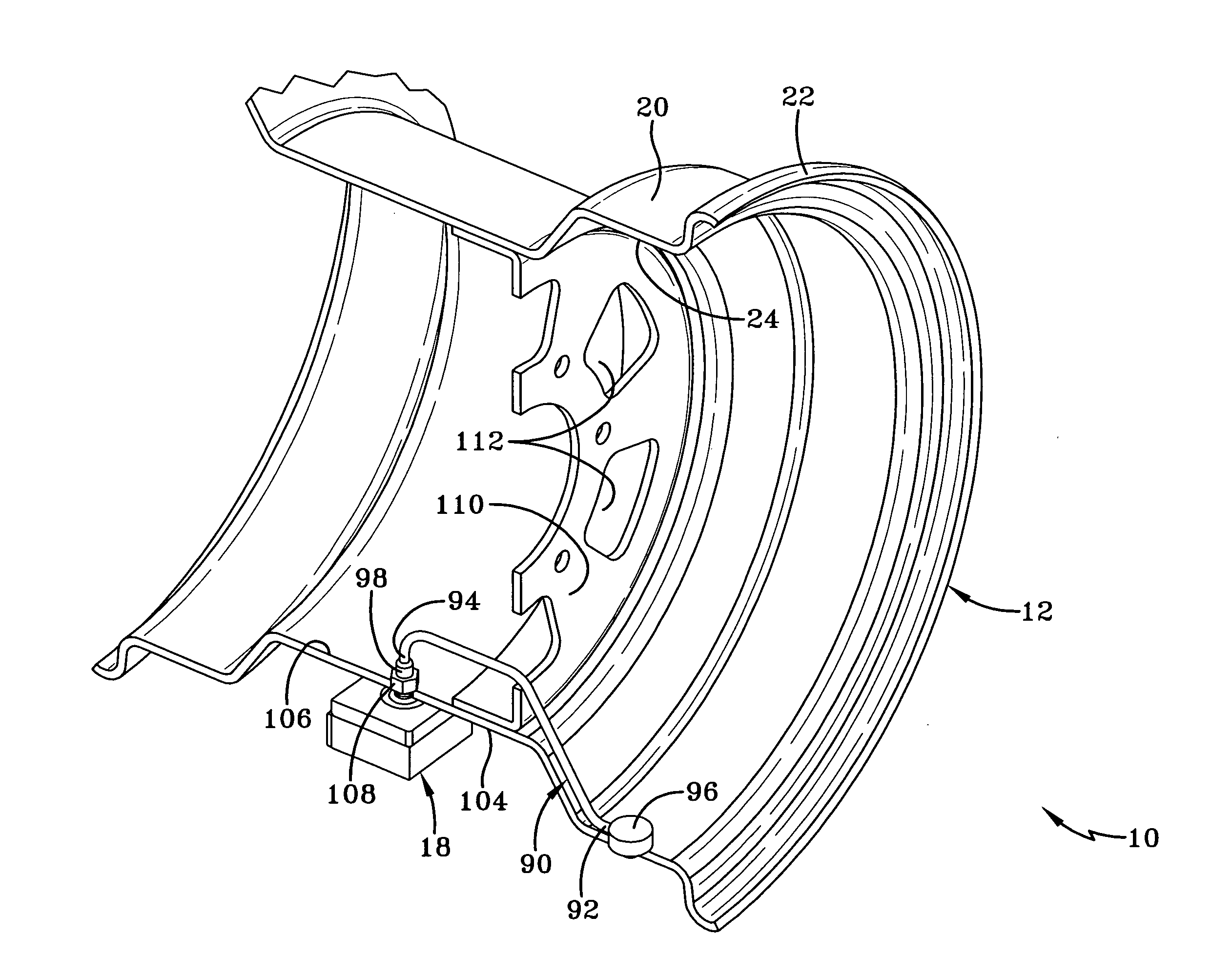
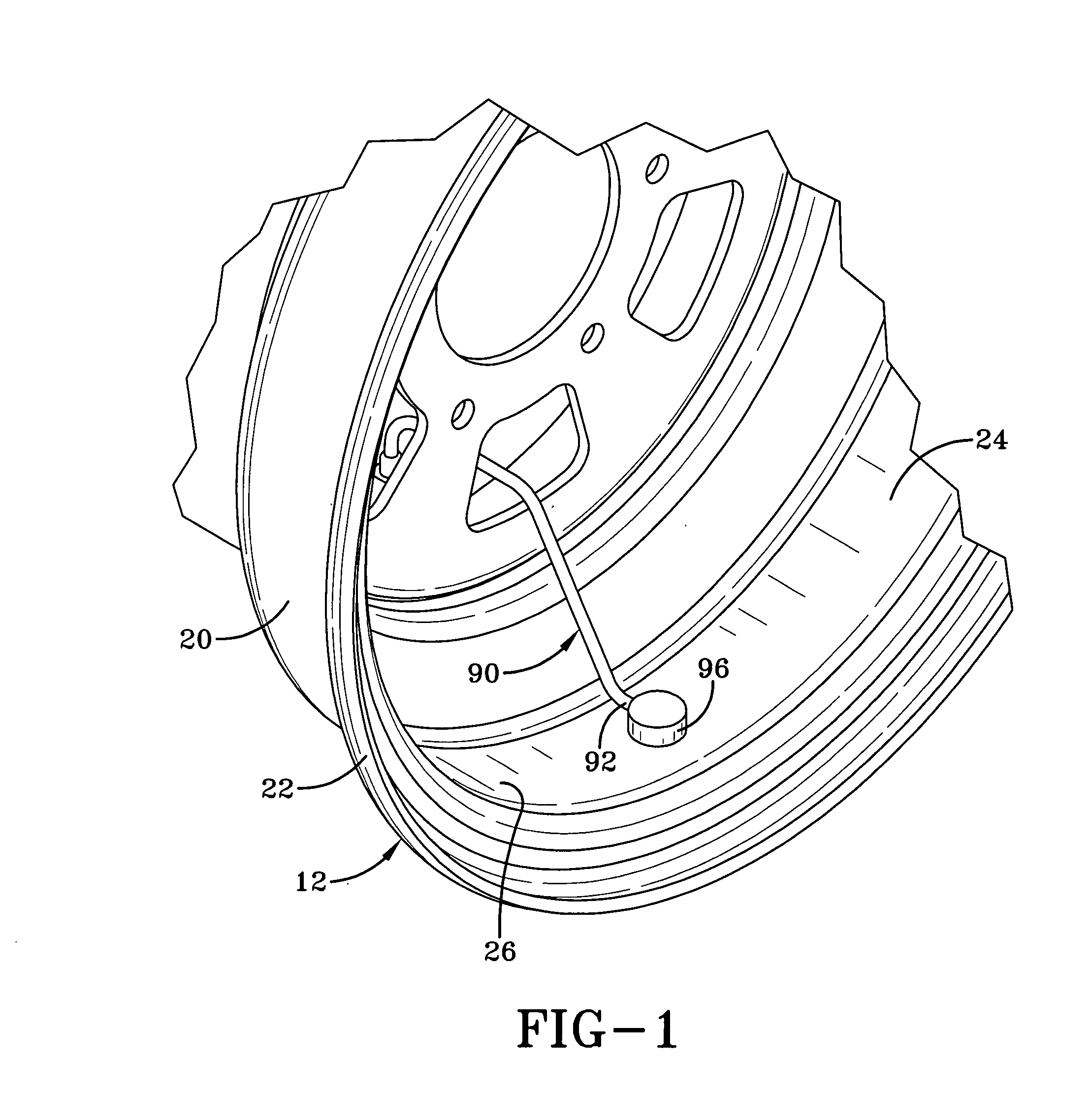
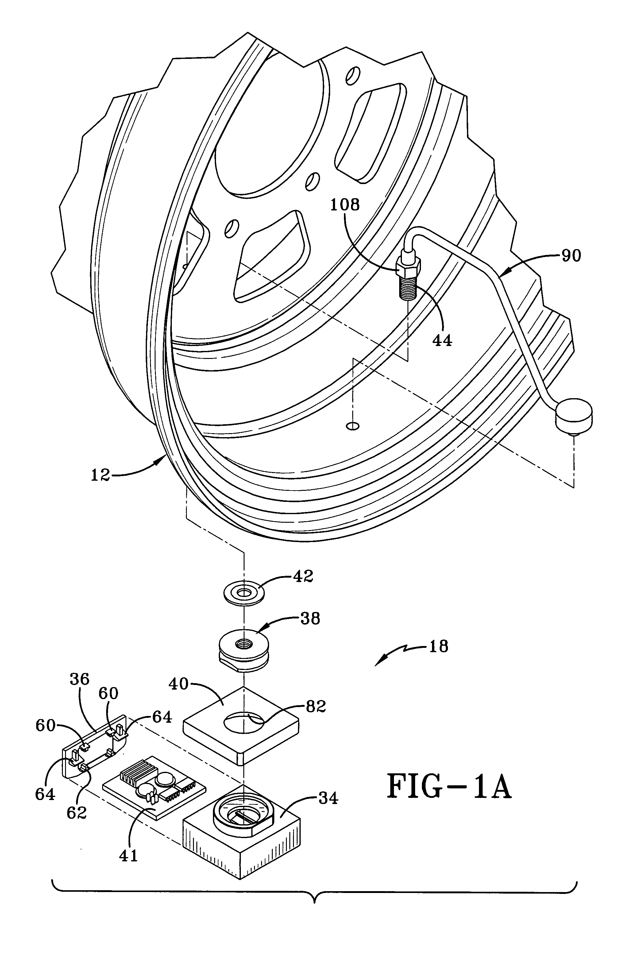
[0033]With reference to FIGS. 1, 1A, 2, 3, and 3A a tire, rim, and tire pressure monitoring module assembly 10 is shown. The rim 12 is of a conventional rim configuration. A two tire system, such as that used in NASCAR racing is depicted for the purpose of illustration, it being understood that the subject rim mounted tire pressure monitoring system is capable of utilization in a single tire and rim application. A pair of spaced apart tire bodies 14, 16 of conventional tire configuration is mounted to the rim 12, the tire body 16 representing an inner tire and the tire body 14 representing an outer tire. The inner tire 16 functions to maintain stability in the event the outer tire 14 is damaged or otherwise deflates. In a two tire system such as that shown, both tires are mounted to a common rim internal surface region 20. With the beads of the tire bodies 14, 16 properly seated on surface 20, the inner tire 16 (which has higher inflation pressure than the outer tire) pushes both be...


PUM


Abstract

A tire and wheel rim assembly includes a tire supporting rim having an outward facing mounting surface and at least one tire body mounted to the rim and positioning an internal tire cavity over the rim mounting surface. A tire pressure monitoring module assembly mounts to the rim mounting surface and includes a housing having an internal pressure chamber; a pressure sensing device and/or a temperature measuring sensor within the housing pressure chamber; and an elongate connecting member extending through the housing and the rim mounting surface. A crossover pipe connects the housing pressure chamber with a remote portion of the rim. The inflation pressure in the tire cavity is transferred through the axial passageway of the crossover pipe to the pressure chamber within the module housing.

Description

FIELD OF THE INVENTION [0001]The invention relates generally to tire pressure monitoring systems and, more specifically, to housing assemblies for such systems.BACKGROUND OF THE INVENTION [0002]Typical commercially available tire pressure monitoring system units are mounted to the inside of a tire in a position from which the air pressure within the tire cavity may be measured. Data representing pressure within the tire is then communicated by a transmitted signal to a reader external to the tire. For example, certain available units integrate a pressure sensing module with the valve stem of a tire. Electronics within the sensor unit measure the air pressure at the valve stem and transmit an appropriate signal to an external receiver. The receiver may be located proximally located to the sensor unit or in a remote location such as the passenger compartment.[0003]While working well, such systems are not useful in meeting the industry's needs in certain applications. For example, in s...

Claims


Application Information

Patent Timeline
Patent Type & Authority Applications(United States)
IPC IPC(8): B60C23/04
CPCB60C5/02B60C23/0408B60C23/0498
Inventor CRANO, RICHARD NICHOLAS
Owner THE GOODYEAR TIRE & RUBBER CO
Why Eureka
Try Eureka