Multiple-spot laser refractive ophthalmic surgery

Active Publication Date: 2013-03-05
CARL ZEISS MEDITEC AG
View PDF23 Cites 6 Cited by
  • Summary
  • Abstract
  • Description
  • Claims
  • Application Information

AI Technical Summary

Benefits of technology

[0008]Therefore, it is an object of the invention to provide an apparatus for refractive ophthalmic surgery by laser radiation of the above-mentioned type such that several focus spots can be used without the above-described disadvantages.
[0010]It is particularly easy to make the beam splitting device leave the cross section unchanged, preferably in the pupil, if the device itself is located in or near the pupil of the beam path. Further, the beam splitting device preferably does not have a focusing effect. It is also convenient to arrange the beam splitting device anterior to scanning elements in the beam direction.
[0014]Particularly uniform distribution of the radiation intensity with the possibility of generating a very great number of secondary beams is possible by the use of a beam splitting device which comprises elements consisting of wedges and planar plates, e.g. in the form of a segmented plate, whose segments alternate between different wedges and planar plate elements.
[0015]In the case of circular deflection of the position of the focus in the processing volume, the multiplicity of generated spots may cause intersecting of the respective, e.g. circular, paths on which the foci are shifted. In order to avoid this, it is convenient to control the angle of separation as a function of the target position of the primary spot. A particularly simple realization of this further embodiment is a beam splitting device which rotates the at least one secondary beam about the primary beam in an adjustable manner. For control, an additional further embodiment may then provide a control unit which controls the rotation synchronously with the shifting of the focus position. This prevents intersecting of paths of the spots of the primary and secondary beams. For example, the spots move on concentric circular paths.

Problems solved by technology

Further, the beam splitting device preferably does not have a focusing effect.

Method used


Image

  • Multiple-spot laser refractive ophthalmic surgery
  • Multiple-spot laser refractive ophthalmic surgery
  • Multiple-spot laser refractive ophthalmic surgery

Examples


Embodiment Construction

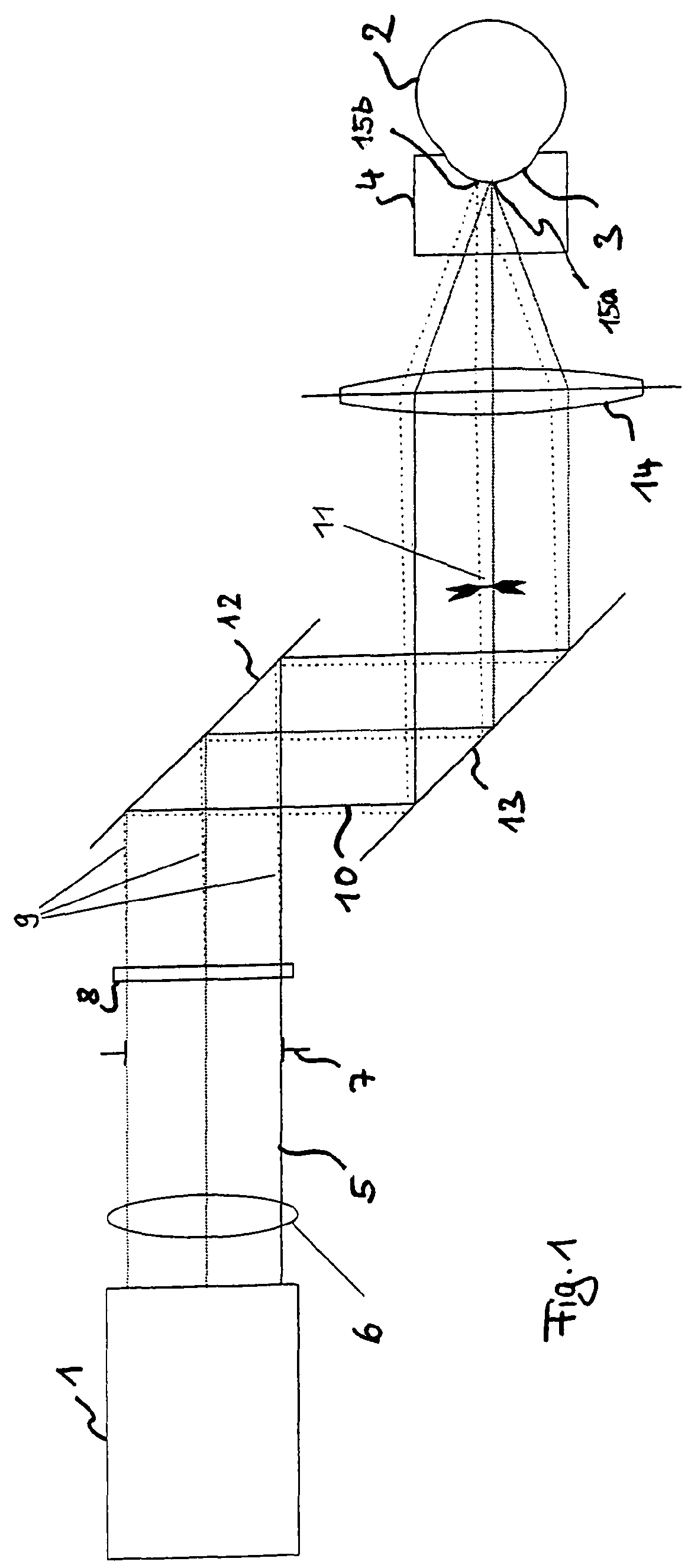
[0033]FIG. 1 shows a laser-surgical system for refraction-correcting treatment of the human eye. The system comprises a source 1 of radiation, which may be provided, for example, as a femtosecond laser, whose radiation is used to process a material, which is the cornea of an eye 2 in the example embodiment described herein. In order to obtain a defined geometrical boundary surface or interface at the cornea 3, a known contact glass 4 is placed on the cornea 3.

[0034]The source 1 of radiation provides a processing beam 5, optionally by the use of optics 6 arranged posterior to the source 1 of radiation. An aperture stop 7 defines the cross section of the beam and the pupil in the beam path that leads to the eye 2. Near the aperture stop 7, i.e. near the pupil, there is a beam splitter 8, which divides the incident processing beam 5 such that a secondary beam 9 is split off, which extends in a slightly different direction to that of the primary beam 10 not being split off. The cross se...


PUM

PropertyMeasurementUnit
wavelength regionaaaaaaaaaa
diameteraaaaaaaaaa
angleaaaaaaaaaa

Abstract

An apparatus for material processing by laser radiation, including a laser source which emits a processing beam, and a beam path for focusing and scanning, the beam path focusing the processing beam into a processing volume and shifting the position of the focus therein. A beam splitting device generates several foci in the processing volume and the beam splitting device splits the processing beam up into a primary beam and at least one secondary beam and leaves the cross section of the beam in a pupil plane of the beam path unchanged during said division and introduces an angle of separation between the primary and secondary beams, so that these beams expand in the beam path in directions which differ by the angle of separation.

Description

PRIORITY CLAIM[0001]The present application is a National Phase Entry of PCT Application No. PCT / EP2008 / 003221, filed Apr. 22, 2008, which claims priority to U.S. Provisional Application No. 60 / 914,182, filed Apr. 26, 2007, and German Application Number 102007019812.6, filed Apr. 26, 2007, the disclosures of which are hereby incorporated by reference herein in their entirety.FIELD OF THE INVENTION[0002]The invention relates to an apparatus for refractive ophthalmic surgery by laser radiation, said apparatus comprising a laser source which emits a processing beam, and a beam path for focusing and scanning, said beam path focusing the processing beam into the cornea of an eye and shifting the position of the focus therein, a beam splitting device being provided to generate several foci in the cornea.BACKGROUND[0003]The processing of material by laser radiation is known. A particular application for processing transparent materials, where a processing effect is obtained by a non-linear...

Claims


Application Information

Patent Timeline
Patent Type & Authority Patents(United States)
IPC IPC(8): A61B18/18
CPCA61F9/00827A61F9/0084B23K26/0604B23K26/0608A61F9/008B23K26/0676G02B26/101G02B27/0905G02B27/0944G02B27/0977B23K26/067A61F2009/00872
Inventor HANFT, MARCOBISCHOFF, MARKWIECHMANN, MARTINSTOBRAWA, GREGORYWITTIG, LARS CHRISTIAN
Owner CARL ZEISS MEDITEC AG
Why Eureka
Try Eureka