
Transformer and flat panel display device including the same

a flat panel display and transformer technology, applied in the direction of static indicating devices, instruments, inductances, etc., can solve the problems of noise generation, difficult to lead and connect the coil to external connection terminals, and the significant narrowness of the coil wound in the transformer

Active Publication Date: 2012-01-05
SOLUM CO LTD
View PDF4 Cites 6 Cited by
  • Summary
  • Abstract
  • Description
  • Claims
  • Application Information

AI Technical Summary

Benefits of technology

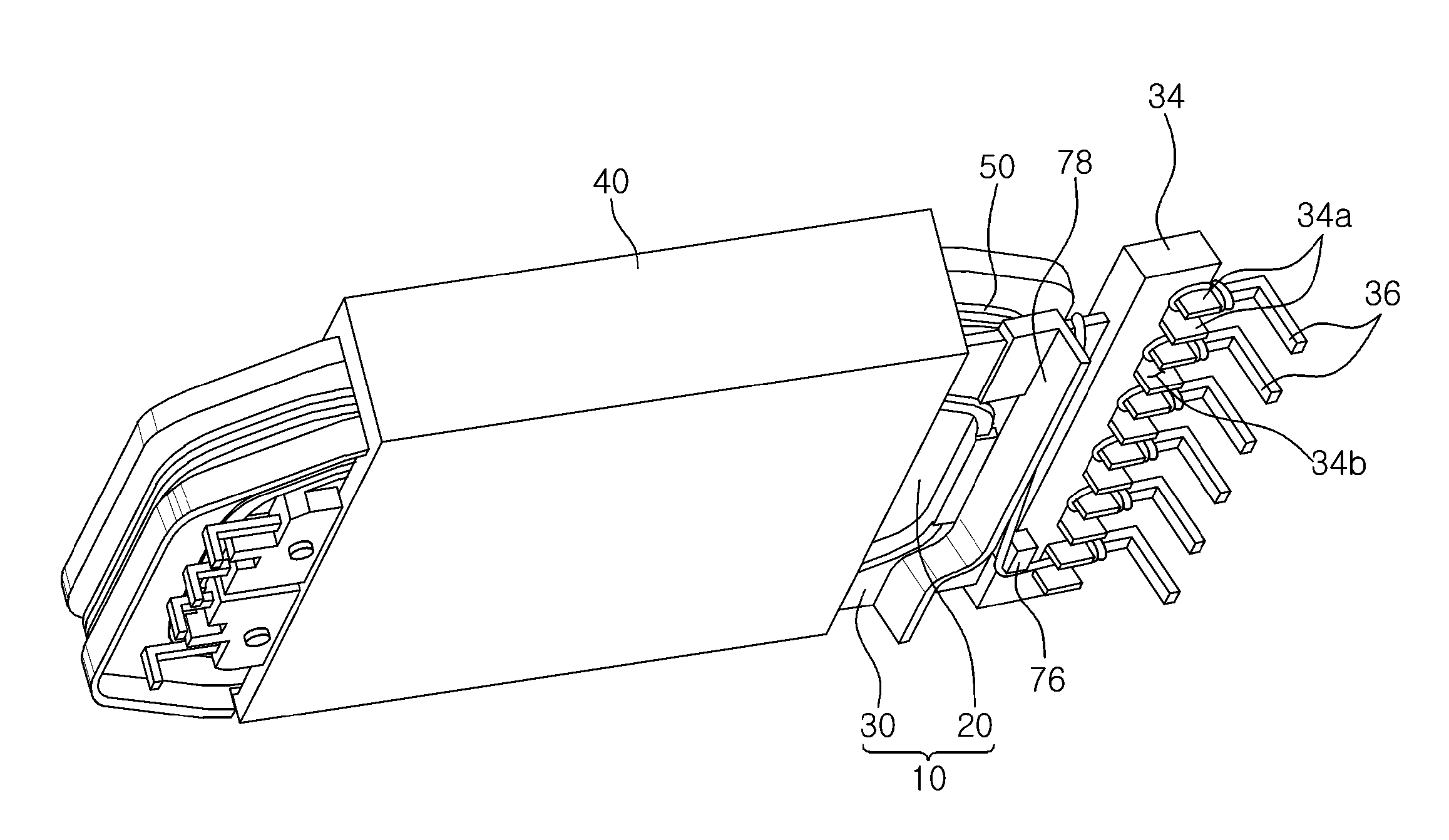
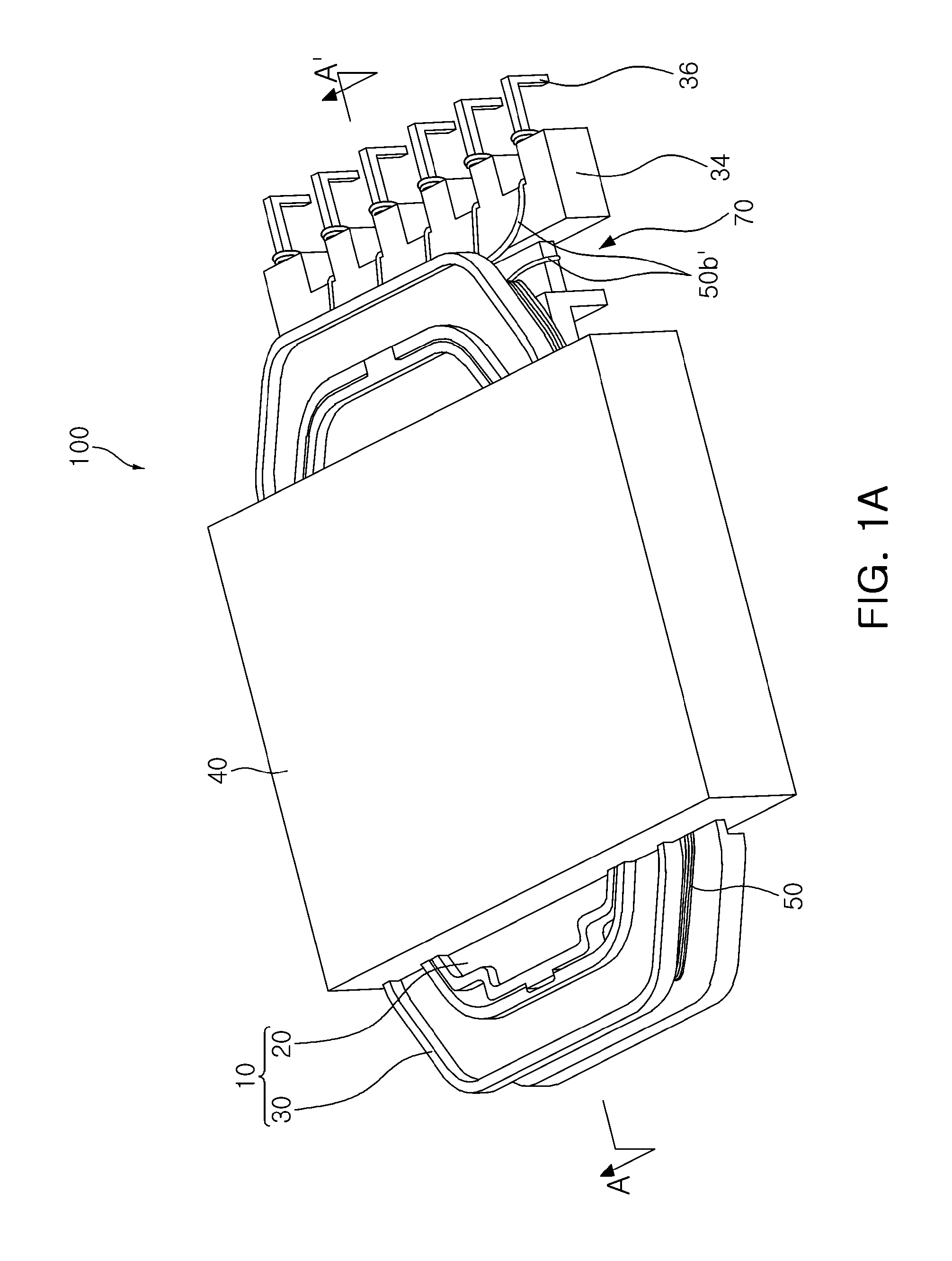
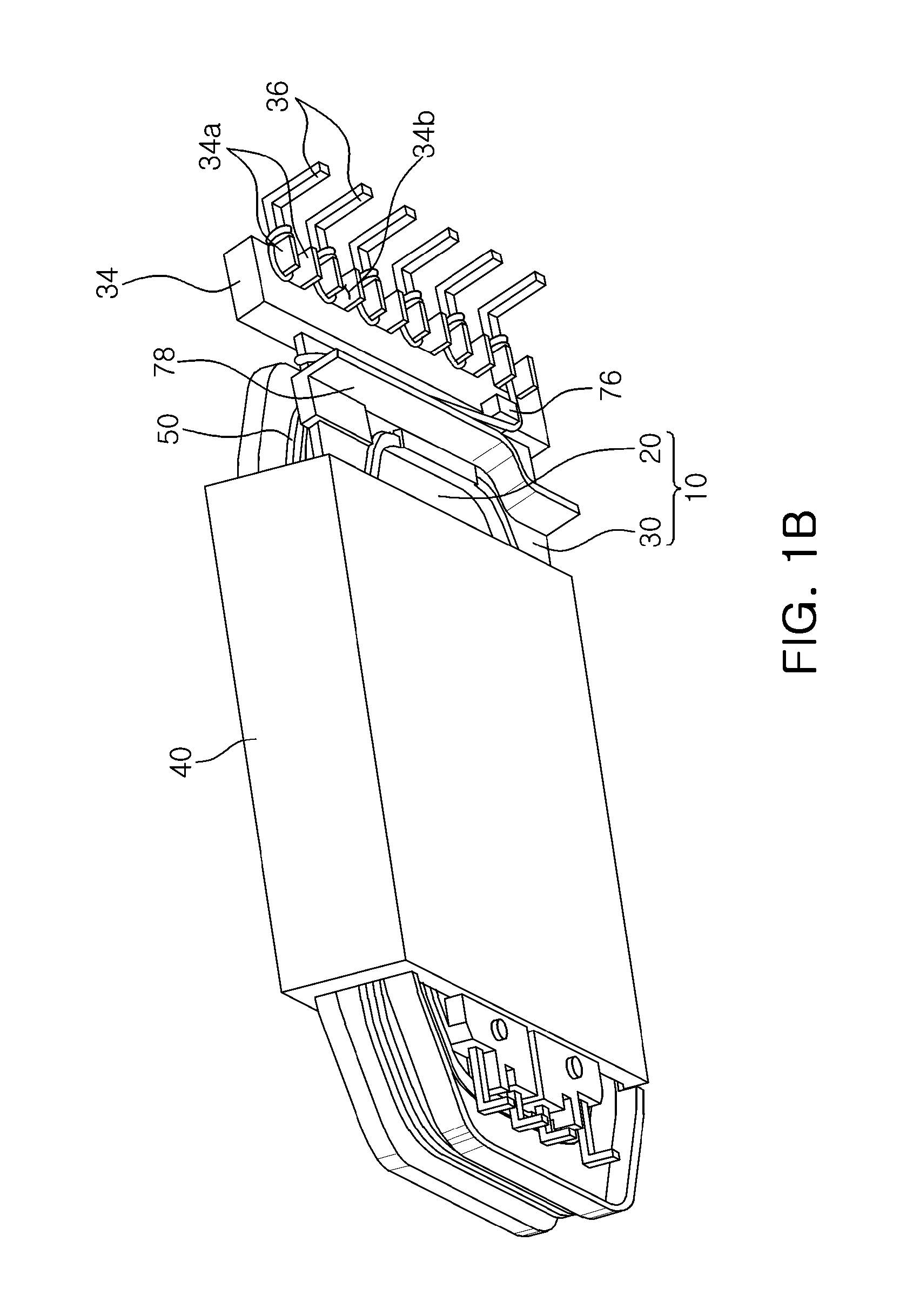
[0029]According to another aspect of the present invention, there is provided a transformer including: a bobbin part including a plurality of bobbins, each including a pipe shaped body part having a though-hole formed in an inner part thereof and a flange part protruding outwardly from both ends of the body part; external connection terminals connected to one end of at least one of the flange parts; and at least one coil wound in a space formed by an outer peripheral surface of the body part and one surface of the flange part, wherein lead wires of the coil are connected to the external connection terminals while being disposed in a distributed scheme on one surface and the other surface of the flange part in order to prevent an intersection therebetween.
[0018]The coil skip part may be a route formed between the terminal connection part and a guide block protruding from the outer surface of the flange part in parallel with the terminal connection part.
[0010]Particularly, when a plurality of coils are connected to the external connection terminals, a case in which they need to be disposed to intersect with each other has occurred. Therefore, the intersected coils are in contact with each other, whereby an electrical short circuit may occur therebetween.
[0011]In the case of the transformer according to the related art, the coils are generally wound perpendicularly to a printed circuit board. In addition, a core is provided in a form in which it forms a magnetic path in parallel with the printed circuit board. Therefore, a magnetic path of a majority of leaked magnetic flux of the transformer is formed through a space between a back cover and the transformer (or a space between the printed circuit board and the transformer).
[0012]Accordingly, in the case of the transformer according to the related art, since the leakage magnetic flux is distributed over the space of the back cover and the transformer, when the back cover and the transformer have a narrow interval therebetween in order to allow a display device to be slim, interference is generated between the back cover formed of a metallic material and the leaked magnetic flux, such that noise is generated while the back cover is vibrated.

Problems solved by technology

However, as a thickness of a transformer is reduced, a movement range of a coil wound in the transformer may become significantly narrow, such that it is difficult to lead and connect the coil to external connection terminals.
Accordingly, in the case of the transformer according to the related art, since the leakage magnetic flux is distributed over the space of the back cover and the transformer, when the back cover and the transformer have a narrow interval therebetween in order to allow a display device to be slim, interference is generated between the back cover formed of a metallic material and the leaked magnetic flux, such that noise is generated while the back cover is vibrated.

Method used


Image

  • Transformer and flat panel display device including the same
  • Transformer and flat panel display device including the same
  • Transformer and flat panel display device including the same

Examples


Embodiment Construction

[0047]The terms and words used in the present specification and claims should not be interpreted as being limited to typical meanings or dictionary definitions, but should be interpreted as having meanings and concepts relevant to the technical scope of the present invention based on the rule according to which an inventor can appropriately define the concept of the term to most appropriately describe the best method he or she knows for carrying out the invention. Therefore, the configurations described in the embodiments and drawings of the present invention are merely the most preferable embodiments but do not represent all of the technical spirit of the present invention. Thus, the present invention should be construed as including all the changes, equivalents, and substitutions included in the spirit and scope of the present invention at the time of the filing of this application.

[0048]Hereinafter, embodiments of the present invention will be described in detail with reference t...


PUM

PropertyMeasurementUnit
vertical thicknessaaaaaaaaaa
magneticaaaaaaaaaa
acute angleaaaaaaaaaa

Abstract

There are provided a thin transformer capable of being used in a slim display device such as a liquid crystal display (LCD) device and a light emitting diode (LED) display device, and a flat panel display device including the same. The transformer includes: a bobbin part including a plurality of bobbins, each including a pipe shaped body part having a though-hole formed in an inner part thereof and a flange part protruding outwardly from both ends of the body part; coils respectively wound around the bobbins; and a core electromagnetically coupled to the coils to thereby form a magnetic path, wherein at least one of the bobbins includes a coil skip part which is a route through which lead wires of the coil skipped through the flange part is disposed on an outer surface of the flange part.

Description

CROSS-REFERENCE TO RELATED APPLICATIONS[0001]This application claims the priority of Korean Patent Application Nos. 10-2010-0063720 filed on Jul. 2, 2010, 10-2010-0138336 filed on Dec. 29, 2010, and 10-2011-0057273 filed on Jun. 14, 2011, in the Korean Intellectual Property Office, the disclosures of which are incorporated herein by references.BACKGROUND OF THE INVENTION[0002]1. Field of the Invention[0003]The present invention relates to a thin transformer capable of being used in a slim display device such as a liquid crystal display (LCD) device and a light emitting diode (LED) display device, and a flat panel display device including the same.[0004]2. Description of the Related Art[0005]Recently, a flat panel display (FPD) which is a new technology appropriate for a multi-media system having a high resolution and a large-sized screen, or the like, has been prominent in the field of displays, instead of a cathode ray tube (CRT).[0006]Particularly, a slim display such as a liquid ...

Claims


Application Information

Patent Timeline
Patent Type & Authority Applications(United States)
IPC IPC(8): H01F19/00G09G5/00H01F27/29
CPCH01F27/29H05B41/02H01F27/325
Inventor CHEON, MYEONG SIKSEO, SANG JOONPARK, GEUN YOUNGKIM, DEUK HOONSHIN, HWI BEOMLEE, YOUNG MINKIM, JONG HAE
Owner SOLUM CO LTD
Learn More