Accumulator cell assembly

A battery and component technology, applied in battery pack components, electrical components, circuits, etc., can solve problems such as large connection impedance and difficulty in reducing impedance, and achieve the effect of increasing current and eliminating connection impedance.

Inactive Publication Date: 2005-12-07
HONDA MOTOR CO LTD
View PDF1 Cites 7 Cited by
  • Summary
  • Abstract
  • Description
  • Claims
  • Application Information

AI Technical Summary

Problems solved by technology

[0010] In addition, since the positive wire portion 303 of one of the adjacent storage batteries 301, 301 is connected to the negative wire portion 304 of the other storage battery 301 in order to conn

Method used


Image

  • Accumulator cell assembly
  • Accumulator cell assembly
  • Accumulator cell assembly

Examples


Embodiment Construction

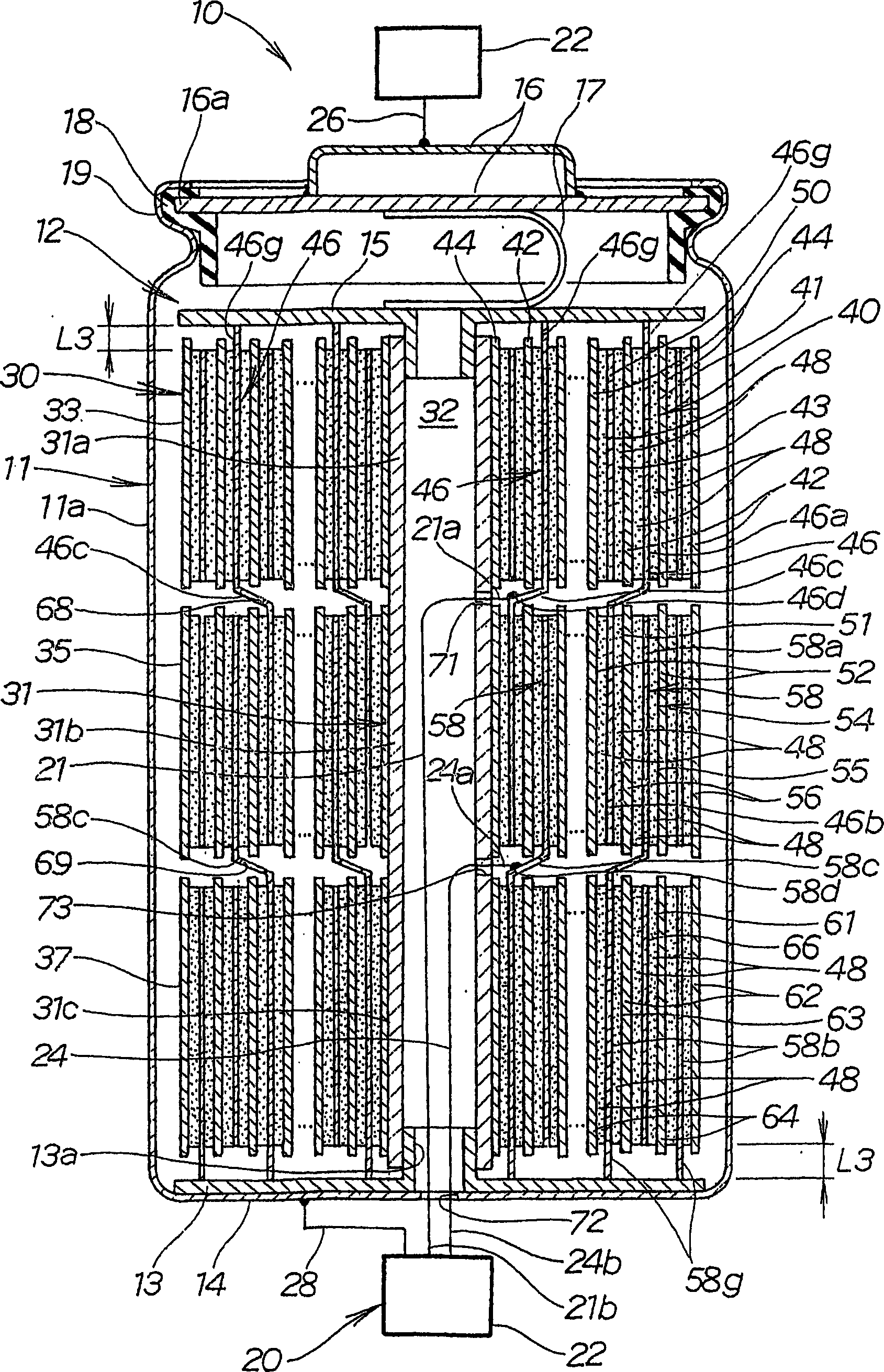
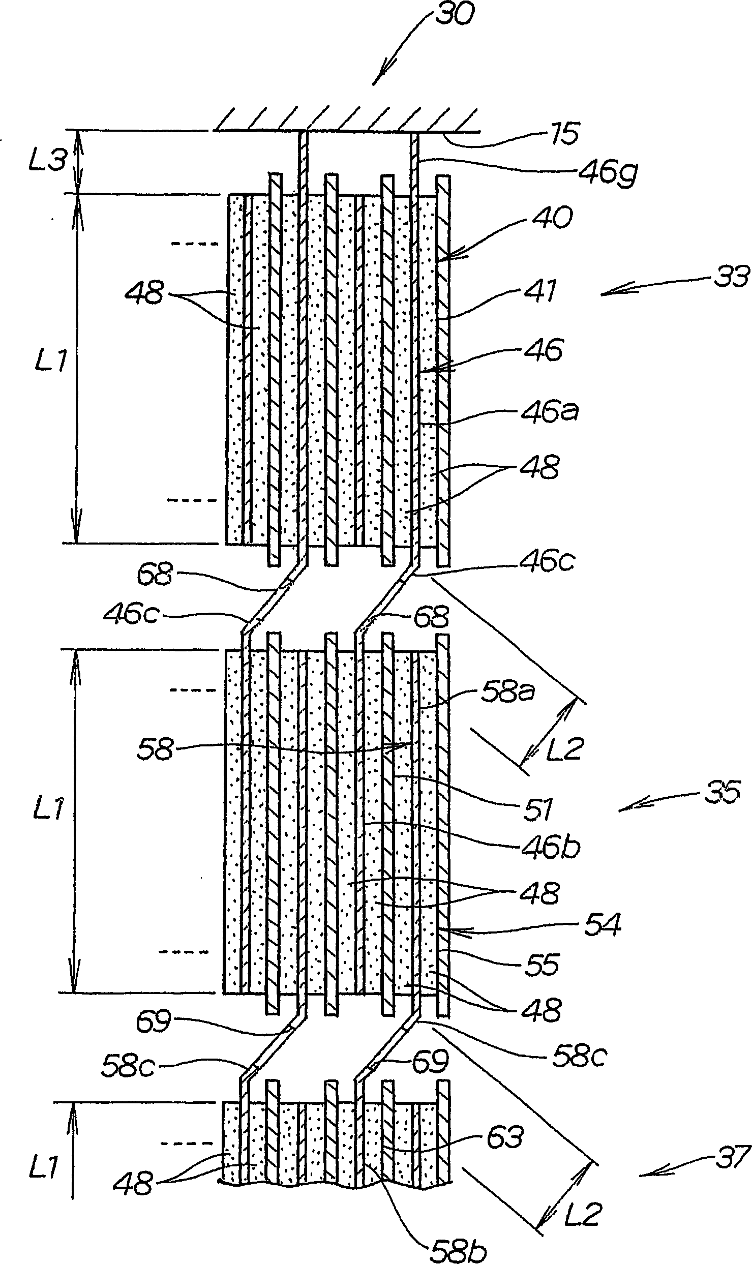
[0042] figure 1 The cylindrical battery 10 shown in has a cylindrical container 11 and a battery cell 12 housed in the cylindrical container 11 . The storage battery unit 12 has a negative electrode current collector plate 13 and a positive electrode current collector plate 15 . The negative electrode collector plate 13 is fixed on the bottom 14 of the cylindrical container 11 . The positive collector plate 15 is connected to the lid portion 16 of the cylindrical container 11 by a conductive U-shaped connector 17 . The cover portion 16 has an insulating rubber ring 18 provided around its outer circumference 16a. The lid 16 is joined to the top 19 by crimping the top 19 of the cylindrical container 11 to the insulating rubber ring 18 . The cylindrical battery 10 has a voltage correction device 20 . This voltage correction device 20 corrects the voltages of the batteries 33 , 35 , and 37 constituting the battery unit 12 . The cover portion 16 serves as a positive electrode....


PUM


Abstract

PROBLEM TO BE SOLVED: To provide a serial connection structure of a storage element in which compactification is enabled by suppressing the length of a cylindrical battery and in which connection resistance can be suppressed.SOLUTION: In the serial connection structure 30 of the storage element, a positive electrode body and a negative electrode body are formed by installing a polarized electrode 48 composed of active carbon, a conductive material and a binding agent at least on one face of current collector foil, the upper storage element 33, the center storage element 35, and the lower storage element 37 are formed by winding the positive electrode body and the negative electrode body in a state of being separated by a separator, and a plurality of the storage elements 33, 35, 37 are connected in series. The serial connection structure 30 of the storage elements is constituted so that first and second enlarged current collector foils 46, 58 with at least twice the width of the polarized electrode 48 are prepared, the first and the second current collector foils 46, 58 are continuously succeeded by neighboring the storage elements, and so that the storage elements are serially connected.

Description

technical field [0001] The present invention relates to a storage battery assembly manufactured by forming a plurality of storage batteries by winding a positive electrode body and a negative electrode body separated by a separator onto a winding core and connecting the storage batteries together in series Forming. Background technique [0002] For example, in JP-A-11-26321 there is proposed a cylindrical battery made by connecting together a plurality of storage batteries storing electric power in batteries and capacitors and the like. FIG. 23 shows such a prior art cylindrical battery with a battery connection structure in series. [0003] Referring to FIG. 23 , a plurality of storage batteries 301 constituting a cylindrical battery 300 are connected in series. These accumulators 301 connected in series are accommodated in a cylindrical metal case 302 . [0004] Each storage battery 301 is a wound body formed by forming polarized electrodes on the surface of a current c...

Claims


Application Information

Patent Timeline
IPC IPC(8): H01G9/26H01G9/048H01G11/10H01G11/12H01G11/42H01G11/66H01G11/70H01G11/72H01G11/74H01G11/78H01M4/64H01M4/70H01M50/503H01M50/514H01M50/528
CPCY02E60/10
Inventor 松本谦治
Owner HONDA MOTOR CO LTD
Why Eureka
Try Eureka