
Non-inverting cross-gain modulation-based wavelength converter

a wavelength converter and non-inverter technology, applied in the field of optical devices, can solve the problems of high cost, limited bandwidth, complex electronic system, etc., and achieve the effect of reducing the cost and improving the efficiency of optical wavelength converters

Inactive Publication Date: 2008-03-11
SANMINA-SCI CORPORATION
View PDF4 Cites 2 Cited by
  • Summary
  • Abstract
  • Description
  • Claims
  • Application Information

AI Technical Summary

Benefits of technology

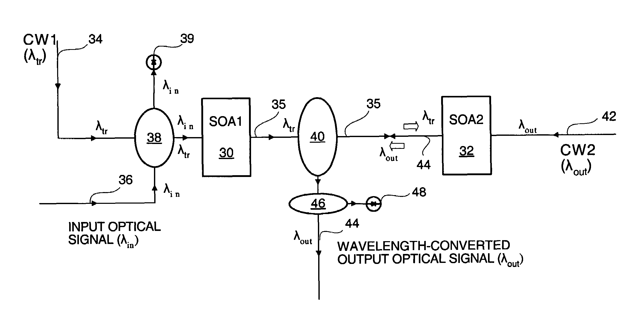
The invention is a wavelength converter and a method for converting the wavelength of an optical data signal using double cross-gain modulation (XGM). The wavelength converter has two semiconductor optical amplifiers (SOAs) to perform a two-stage XGM modulation. The first SOA performs a first cross-gain modulation on a first continuous wave light using an input light with input wavelength for modulation. The second SOA performs a second cross-gain modulation on the first cross-gain modulated light for producing an output light with an output wavelength. The method uses the wavelength converter to convert the wavelength of an optical data signal and generate an output optical data signal with non-inverted signal modulations. The wavelength converter and method can be used in various optical communication systems to compensate for wavelength-dependent gain variance.

Problems solved by technology

Problems with OEO-based wavelength converters include high costs, complexity of electronic systems, and limited bandwidth.
As the data bit rate continues to increase, the bandwidth limitation in particular is a growing barrier for OEO-based wavelength converters.
This type of optical wavelength converters, however, are not highly suitable for converting wavelengths of coherent light sources.
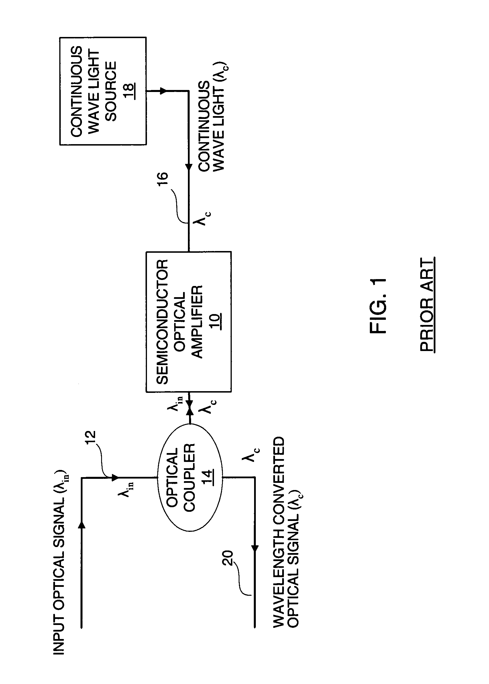
Several problems still exist with prior art XGM-based wavelength converters shown in FIG. 1.
One problem is that cross-gain modulation (XGM) inverts the output signal with respect to the input signal.
This inversion often necessitates further data manipulation.
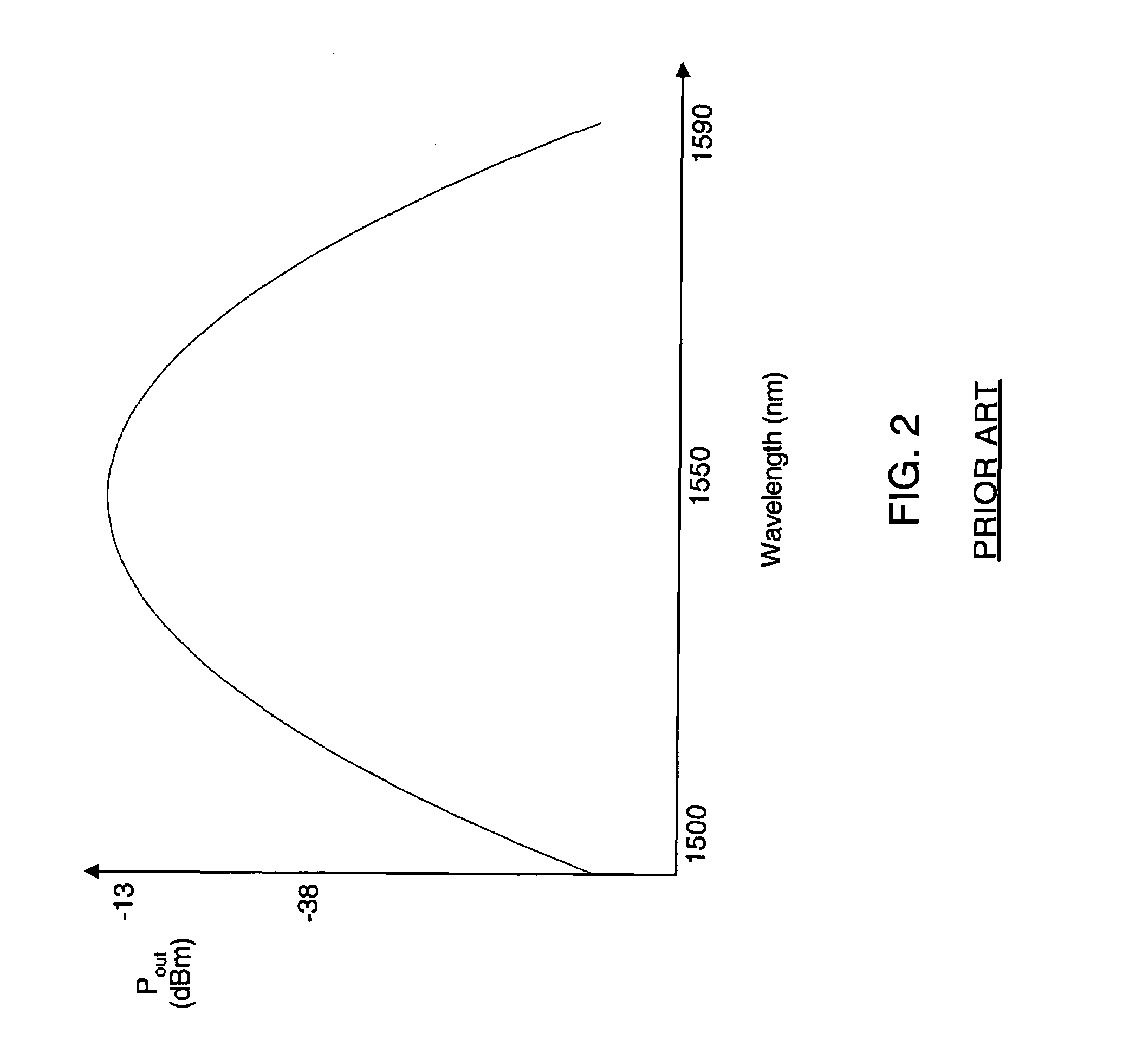
Another problem is that XGM exhibits uneven conversion among different wavelengths, and accordingly an XGM-based wavelength converter has an output performance which is wavelength dependent.
Both the above identified problems are inherent to single cross-gain modulation.

Method used


Image

  • Non-inverting cross-gain modulation-based wavelength converter
  • Non-inverting cross-gain modulation-based wavelength converter
  • Non-inverting cross-gain modulation-based wavelength converter

Examples


Embodiment Construction

[0028]The present inventions provide a wavelength converter and a method for changing the wavelength of an optical signal. Those skilled in the art will recognize that various features disclosed in connection with the embodiments may be used either individually or jointly. It is to be appreciated that while the present inventions have been described with reference to preferred implementations, those having ordinary skill in the art will recognize that the present inventions may be beneficially utilized in any number of environments and implementations.

[0029]The inventions have been described below with reference to specific embodiments. It will be readily appreciated by those skilled in the art that various modifications may be made and other embodiments can be used without departing from the broader scope of the inventions. Therefore, these and other variations upon the specific embodiments are intended to be covered by the present inventions.

[0030]The invention provides a waveleng...


PUM


Abstract

Wavelength converter and methods are based on cross-gain modulation. The wavelength converter has two semiconductor optical amplifiers to perform double cross-gain modulations and double inversions. The first semiconductor optical amplifier performs a first cross-gain modulation on a first continuous wave light using the input light as a modulating light to generate an inverted first-stage cross-gain modulated light. The second semiconductor optical amplifier performs a second cross-gain modulation on a second continuous wave light using the first-stage cross-gain modulated light as a modulating light to generate a double-inverted output light. The output light is non-inverted with respect to the input light.

Description

BACKGROUND[0001]1. Field of the Invention[0002]The present invention relates generally to optical devices, and more particularly to cross-gain modulation type wavelength converters to change the wavelength of an incoming signal.[0003]2. Description of the Prior Art[0004]A wavelength converter converts a data signal at one wavelength to the same data signal at another wavelength. Wavelength converters are an important part of modern data communications networks. Wavelength converters are used when the wavelength of the carrier light wave needs to be changed at some points in the communications network.[0005]There are two major types of wavelength converters used in digital data communications systems. The first type involves optical-electrical-optical (OEO) conversions in which the wavelength converter first converts an input light (optical) signal at an input wavelength to electrical signals, and then generates an output light (optical) signal at an output wavelength using the elect...

Claims


Application Information

Patent Timeline
Patent Type & Authority Patents(United States)
IPC IPC(8): H01S3/00
CPCH01S5/50H01S5/028H01S5/5027H01S5/509
Inventor CHAPUT, BRIAN
Owner SANMINA-SCI CORPORATION
Learn More