
Instantaneous microwave frequency measurement device and method based on dispersion Fourier transform

A technology of microwave frequency measurement and Fourier transform, which is applied in the field of microwave photonics, can solve the problems of mutual restriction between the measurement frequency range and precision, the inability to realize multi-tone microwave measurement, and the inability to measure multi-tone signals, so as to overcome the measurement blind zone , The effect of reducing measurement error and improving measurement resolution

Active Publication Date: 2020-11-06
CHONGQING UNIV OF POSTS & TELECOMM
View PDF5 Cites 1 Cited by
  • Summary
  • Abstract
  • Description
  • Claims
  • Application Information

AI Technical Summary

Problems solved by technology

Among them, the frequency-space mapping method realizes the measurement of the microwave frequency by mapping the microwave frequency to different positions or channels in the space. The frequency-time mapping method is to use the principle that different microwave frequency components obtain different delays after passing through the same dispersion medium, and obtain the microwave frequency to be measured by calculating the relative delay. The measurement range and measurement accuracy are the same as the selected dispersion The medium is related and mutually restricted; the microwave frequency measurement technology based on the frequency-amplitude mapping method maps the microwave frequency and the received microwave or light wave power. This scheme has good reconfigurability, and the frequency measurement accuracy reaches 0.2 GHz, but it also faces the problem of mutual constraints between the measurement frequency range and accuracy, and at the same time, this solution cannot measure multi-tone signals
Recently, some scholars have proposed the use of optical frequency comb mixing technology (G.Q.Hu, T.Mizuguchi, X.Zhao, T.Minamikawa, T.Mizuno, Y.L.Yang, C.Li, M.Bai, Z.Zheng, and T. Yasui, "Measurement of absolute frequency of continuous-wave terahertzradiation in real time using a free-running, dual-wavelength mode-locked, erbium-doped fiber laser," Sci.Rep.7, 42082(2017)), by analyzing the minimum Mixing frequency components realizes the measurement of the microwave frequency to be measured. This scheme has the advantages of wide measurement frequency range, high measurement accuracy and real-time measurement. However, this scheme has measurement blind spots, requires two or more optical frequency combs, and cannot realize multi-tone Disadvantages of Microwave Measurements

Method used


Image

  • Instantaneous microwave frequency measurement device and method based on dispersion Fourier transform
  • Instantaneous microwave frequency measurement device and method based on dispersion Fourier transform
  • Instantaneous microwave frequency measurement device and method based on dispersion Fourier transform

Examples


Embodiment 1

[0070] Single frequency microwave signal measurement

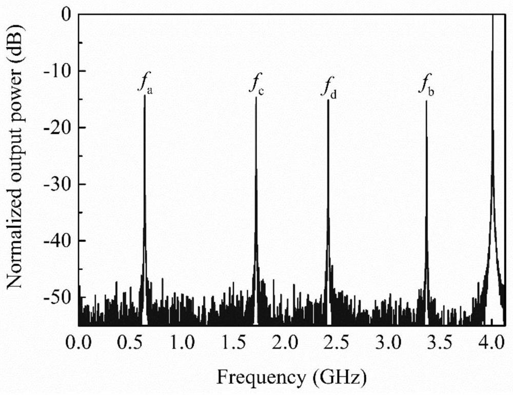
[0071] Assuming that the frequency of the microwave signal to be tested is 55.5GHz, the repetition frequency f of the ultrashort optical pulse source r1 4.01GHz respectively, adjust the length of the single-mode fiber at both ends so that its stretching factor M=1.032, at this time the equivalent optical frequency comb repetition frequency f r2 It is 4.137GHz, and the spectrum resolution of the spectrum analysis module is 0.5MHz. Such as figure 2 As shown, obtain f a +f b = f r1 and f c +f d = f r2 The frequency of the mixing signal is f a =3.37GHz, f b = 0.64GHz, f c = 1.719GHz and f d = 2.418GHz. At this time, there is a positive integer N=13, so that |f a -f c |=N×Δf and |f b -f d |=(N+1)×Δf, then the measured frequency f s =N×f r1 +f a =(13*4.01+3.37)GHz=55.5GHz. The measured microwave frequency value is consistent with the frequency of the microwave signal to be measured, which verifies the accura...

Embodiment 2

[0073] Multi-tone microwave signal measurement

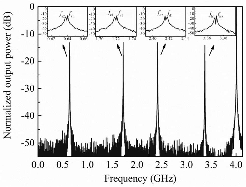
[0074] Assuming that the frequency of the microwave signal to be measured is 55.5GHz and 55.502GHz, the repetition frequency f of the ultrashort optical pulse source r1 4.01GHz respectively, adjust the length of the single-mode fiber at both ends so that its stretching factor M=1.032, at this time the equivalent optical frequency comb repetition frequency f r2 It is 4.137GHz, and the spectrum resolution of the spectrum analysis module is 0.5MHz. Such as image 3 As shown, obtain f a1 +f b1 = f r1 and f c1 +f d1 = f r2 The frequency of the mixing signal is f a1 =3.37GHz, f b1 = 0.64GHz, f c1 = 1.719GHz and f d1 =2.418GHz, satisfy f a2 +f b2 = f r1 and f c2 +f d2 = f r2 The frequency of the mixing signal is f a2 =3.372GHz, f b2 = 0.638GHz, f c2 = 1.721GHz and f d2 = 2.416GHz. At this time, there is a positive integer N=13, so that |f a1 -f c1 |=N 1 ×Δf and |f b1 -f d1 |=(N 1 +1)×Δf, then the frequency t...


PUM


Abstract

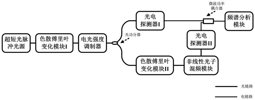
The invention discloses an instantaneous microwave frequency measurement device and method based on dispersion Fourier transform, which belong to the technical field of microwave photons, and are mainly applied to measurement of instantaneous microwave signal frequency. The device comprises an ultra-short pulse light source, a dispersion Fourier transform module I, an electro-optical intensity modulator, an optical power divider, a dispersion Fourier transform module II, a nonlinear photon mixing module, a photoelectric detector I, a photoelectric detector II, a microwave power coupler and a spectrum analysis module. The dispersion Fourier transform modules are dispersion mediums, can be single-mode fibers or fiber Bragg gratings, and are used for realizing optical pulse width stretching and broadening of the ultra-short pulse light source. The nonlinear photon frequency mixing module realizes photon frequency mixing by utilizing nonlinear effects such as a cross gain modulation effectand a four-wave frequency mixing effect, and can be a high nonlinear optical fiber or a nonlinear semiconductor optical amplifier. The device and the method have the advantages of instantaneity, multi-tone, broadband, high precision and no blind area frequency measurement.

Description

technical field [0001] The invention belongs to the field of microwave photonics, and in particular relates to an instantaneous microwave frequency measurement technology based on dispersion Fourier transform time stretching frequency reduction. Background technique [0002] Microwave / millimeter wave technology is more and more widely used in national defense technology, microwave communication, industrial and agricultural production, and daily life, especially in the fields of electronic warfare, radar early warning, wireless communication and space communication. As microwave operating frequencies in various application fields gradually expand to high frequency bands (even as high as 300 GHz), due to the limitation of electronic bottlenecks and instantaneous bandwidth, the real-time measurement and analysis of microwave signals using traditional electronic domain frequency measurement technology appears to be powerless. It is particularly important to develop the correspon...

Claims


Application Information

Patent Timeline
IPC IPC(8): H04B10/079H04B10/2575H04B10/70
CPCH04B10/0795H04B10/25752H04B10/70
Inventor 邹新海亓林郭俊启黎人溥刘宇
Owner CHONGQING UNIV OF POSTS & TELECOMM
Learn More