Fiber optic phased array and associated method for accommodating atmospheric perturbations with phase and amplitude control

a fiber optic and phased array technology, applied in the field of laser systems, can solve the problems of unsatisfactory alteration of the phase and/or amplitude of the optical signal, wavefront zero intensity, optical signals incident upon the target may not have the desired amplitude, etc., to achieve the maximum efficiency of concentrating energy and increase power

Active Publication Date: 2008-03-11
THE BOEING CO
View PDF10 Cites 17 Cited by
  • Summary
  • Abstract
  • Description
  • Claims
  • Application Information

AI Technical Summary

Benefits of technology

[0012]An improved fiber optic phased array and associated control method are therefore provided for controllably adjusting the phase and amplitude of the optical signals emitted by a plurality of fiber optic amplifiers so as to compensate for the otherwise deleterious effects of atmospheric turbulence. By controlling both the amplitude and phase front of the optical signals, the fiber optic phased array and associated method of the present invention can illuminate the target with optical signals of a desired amplitude, notwithstanding atmospheric turbulence. Moreover, the fiber optic phased array and associated control method repeatedly and controllably alter both the phase and the amplitude of the optical signals emitted by the fiber optic amplifiers to thereby take into account variations in the atmospheric turbulence over time.
[0015]The fiber optic phased array also includes a gain adjustment mechanism for controllably altering the amplitude of the optical signals propagating along respective fiber optic amplifiers in response to the amplitude of the optical signals reflected by the target and detected by the sensor assembly, such as the amplitude sensor. For example, the gain adjustment mechanism may include a plurality of pump sources for controllably pumping respective fiber optic amplifiers. Thus, the gain adjustment mechanism can controllably alter the amplitude of the optical signals emitted by the fiber optic amplifiers to compensate for the effects upon the amplitude that will be occasioned by the downstream atmospheric turbulence.
[0019]According to another aspect of the present invention, a method of controllably illuminating a target is provided. Initially, optical signals that are propagating along a plurality of fiber optic amplifiers are amplified. The phase of the optical signals emitted by respective fiber optic amplifiers and transmitted toward the target is then detected. Subsequently, both the phase and the amplitude of the optical signals that have been reflected by the target are detected. Based upon the phase of the optical signals emitted by the respective fiber optic amplifiers and transmitted toward the target and the phase of the optical signals must have been reflected by the target, the phase of the optical signals propagating along respective fiber optic amplifiers is controllably altered. Additionally, the amplitude of the optical signals propagating along the fiber optic amplifiers may be similarly controllably altered in response to the amplitude of the optical signals reflected from the target. In this regard, the amplitude of the optical signals propagating along the respective fiber optic amplifiers may be altered by controllably pumping respective fiber optic amplifiers. As such, the method of this aspect of the present invention can compensate for the otherwise deleterious effects upon both phase and frequency occasioned by atmospheric turbulence.
[0020]Accordingly, the fiber optic phased array and associated method of the present invention can more precisely illuminate a target, both in terms of the phase and amplitude of the optical signal, even as the atmospheric turbulence varies. Additionally, the fiber optic phased array and associated method can reduce, if not eliminate, phase nulls and can therefore increase the power with which the target is illuminated.

Problems solved by technology

Once the output optical signals have been emitted by the laser device, atmospheric turbulence or other perturbations may undesirably alter the phase and / or amplitude of the optical signals prior to reaching the target.
Thus, even if the laser device is controlled so as to emit optical signals having the desired amplitude and phasefront, the optical signals that are incident upon the target may not have the desired amplitude as a result of atmospheric turbulence.
Additionally, the atmospheric turbulence may create regions within the wavefront having zero intensity, i.e., intensity nulls.
Futhermore, scintillation and associated branch points can have a profound reduction in the accuracy with which a wavefront sensor measures the wavefront phase resulting in severe drops in Strehl.

Method used


Image

  • Fiber optic phased array and associated method for accommodating atmospheric perturbations with phase and amplitude control
  • Fiber optic phased array and associated method for accommodating atmospheric perturbations with phase and amplitude control
  • Fiber optic phased array and associated method for accommodating atmospheric perturbations with phase and amplitude control

Examples


Embodiment Construction

[0024]The present invention now will be described more fully hereinafter with reference to the accompanying drawings, in which preferred embodiments of the invention are shown. This invention may, however, be embodied in many different forms and should not be construed as limited to the embodiments set forth herein; rather, these embodiments are provided so that this disclosure will be thorough and complete, and will fully convey the scope of the invention to those skilled in the art. Like numbers refer to like elements throughout.

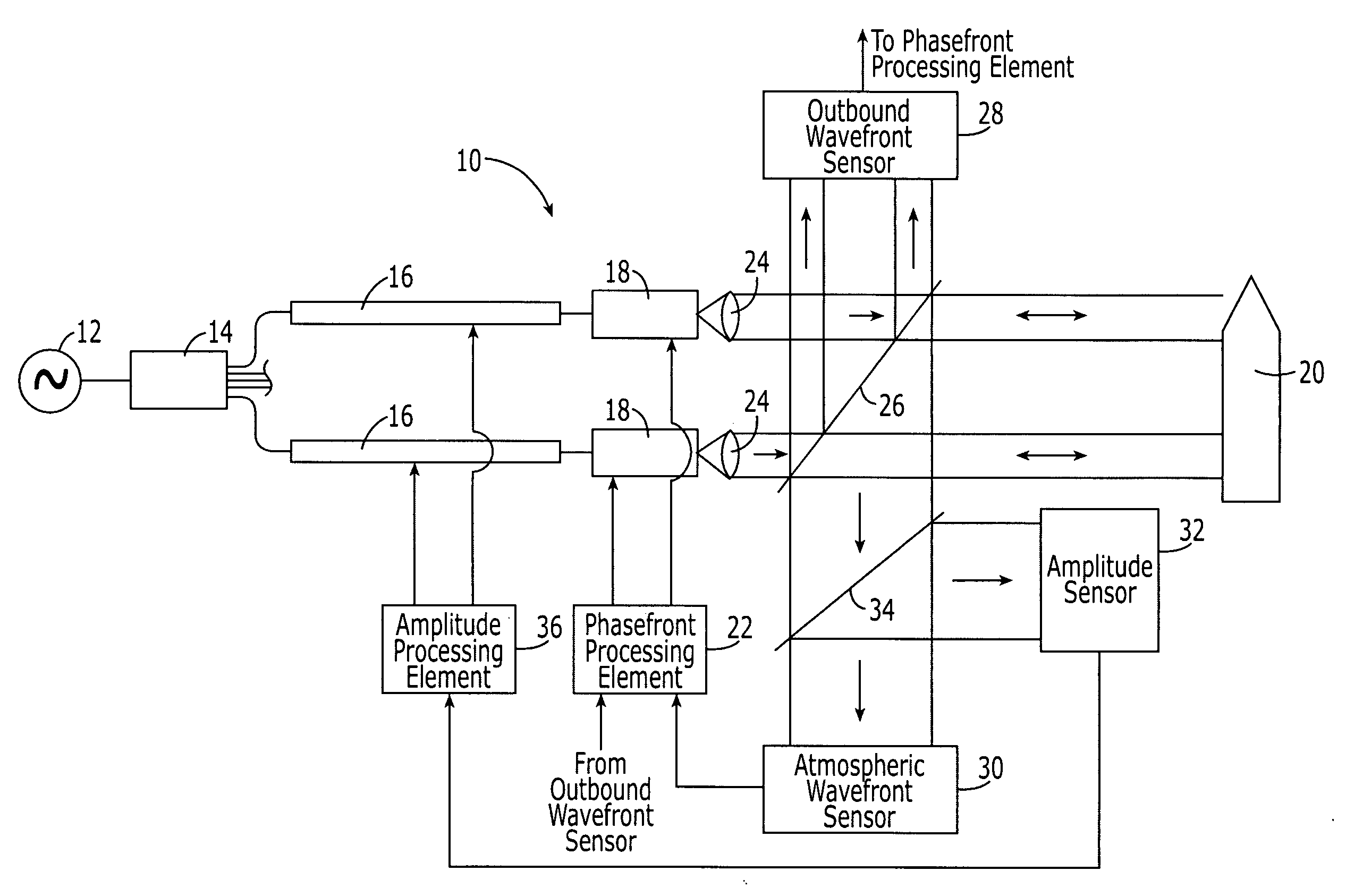
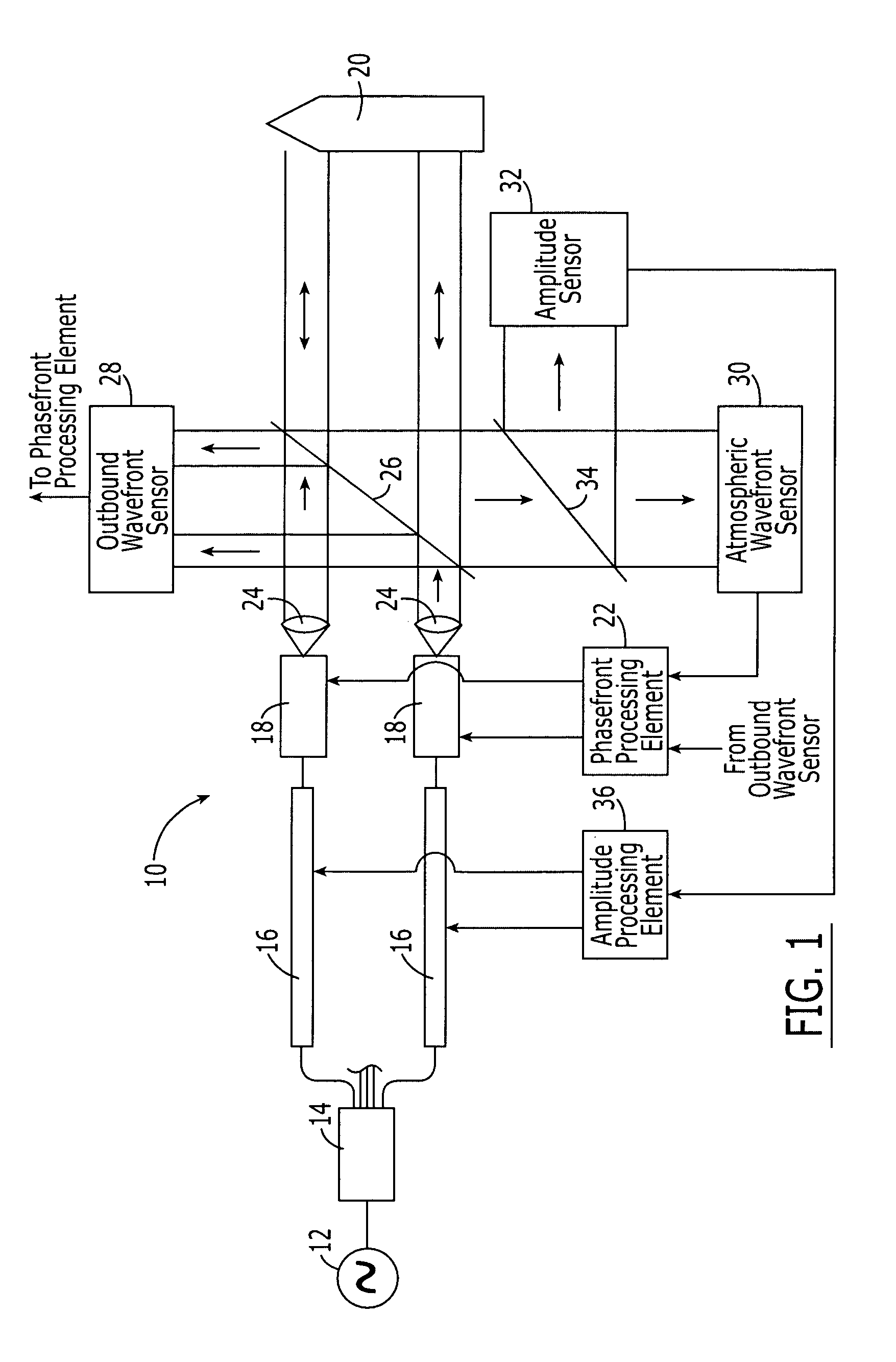
[0025]Referring now to FIG. 1, a fiber optic phased array 10 according to one aspect of the present invention is depicted. The fiber optic phased array 10 is depicted in which an optical signal from a master oscillator 12 is split one or more times and then amplified. The amplified optical signals may then be combined, if desired, to produce an output optical signal having a greater power level than that originally provided by the master oscillator. Althou...


PUM


Abstract

A fiber optic phased array and control method are provided for controllably adjusting the phase and amplitude of the optical signals emitted by a plurality of fiber optic amplifiers to compensate for atmospheric turbulence. The fiber optic phased array also includes a sensor assembly for detecting: (i) the phase of the optical signals that are emitted by the fiber optic amplifiers, and (ii) both the phase and the amplitude of the optical signals that have been reflected by the target. The fiber optic phased array also includes phase modulators and a gain adjustment mechanism for altering the phase and the amplitude of the optical signals propagating along the fiber optic amplifiers to compensate for modifications in the phase and amplitude that will be introduced by atmospheric turbulence. Among other things, the amplitude control of the optical signals is not adversely effected by intensity nulls in the reflected wavefront.

Description

FIELD OF THE INVENTION[0001]The present invention relates generally to laser systems and, more particularly, to a fiber optic phased array and associated method for accommodating atmospheric perturbations with phase and amplitude control.BACKGROUND OF THE INVENTION[0002]Lasers are presently employed for a wide variety of applications. For example, lasers are employed to process materials, such as by cutting, welding, heat treating, drilling, trimming and coating materials, stripping paint, removing coatings, cleaning surfaces, and providing laser markings. Lasers are also used in many medical applications for precision surgery. Additionally, lasers are used in military applications, including laser weapon and laser ranging systems. Laser communication systems have also been developed in which laser signals are transmitted in a predetermined format to transmit data.[0003]Along with the ever increasing number of applications in which lasers are used, the demands on the laser systems a...

Claims


Application Information

Patent Timeline
Patent Type & Authority Patents(United States)
IPC IPC(8): H04B10/00H01Q3/26H01S3/067H01S3/23H04B10/04
CPCH01Q3/2676H01S3/06754H01S3/2383H01S3/10053
Inventor GERWE, DAVID RODERICKRICE, ROBERT R.SCHALL, HAROLD B.
Owner THE BOEING CO
Why Eureka
Try Eureka