
Low complexity classification from a single unattended ground sensor node

a sensor node, low complexity technology, applied in the field of sensor systems, can solve the problems of low computational complexity, low complexity of mvg classifier, low priority of preprocessed data, etc., and achieve the effect of reducing bandwidth and facilitating the selection of classifiers

Active Publication Date: 2008-03-11
ARMY US SEC THE
View PDF19 Cites 17 Cited by
  • Summary
  • Abstract
  • Description
  • Claims
  • Application Information

AI Technical Summary

Benefits of technology

[0019]There are several advantages of the invention. For example, the invention provides low bandwidth exfiltration to the next level for cluster-level or network level classification enhancement. Also, the invention retains use of the vast expertise gained in feature extraction development for certain individual modalities. Additionally, the invention adds to the “toolbox” of conventional classifiers, both for fusion of such classifiers and for greater choice of classifiers to fit to a particular application.

Problems solved by technology

However, minimizing read only memory (ROM) storage of offline, preprocessed data is of lower priority.
However, there is a conflict between the requirement of low computational complexity and the need to classify in high dimensional feature spaces.
Due to this quadratic dependence on d, the MVG classifier is of low complexity for those cases for which d is not too large, but for large values of d it can rapidly become a high complexity classifier.
However, these traditional techniques may encounter difficulties as d increases.
However, a nonlinear SVM classifier cannot compete with an MVG classifier in terms of query complexity alone unless nSV≦O(d).
Nevertheless, whether or not a nonlinear SVM is of low complexity appears to be application dependent.

Method used


Image

  • Low complexity classification from a single unattended ground sensor node
  • Low complexity classification from a single unattended ground sensor node
  • Low complexity classification from a single unattended ground sensor node

Examples


Embodiment Construction

[0030]The invention and the various features and advantageous details thereof are explained more fully with reference to the non-limiting embodiments that are illustrated in the accompanying drawings and detailed in the following description. It should be noted that the features illustrated in the drawings are not necessarily drawn to scale. Descriptions of well-known components and processing techniques are omitted so as to not unnecessarily obscure the invention. The examples used herein are intended merely to facilitate an understanding of ways in which the invention may be practiced and to further enable those of skill in the art to practice the invention. Accordingly, the examples should not be construed as limiting the scope of the invention.

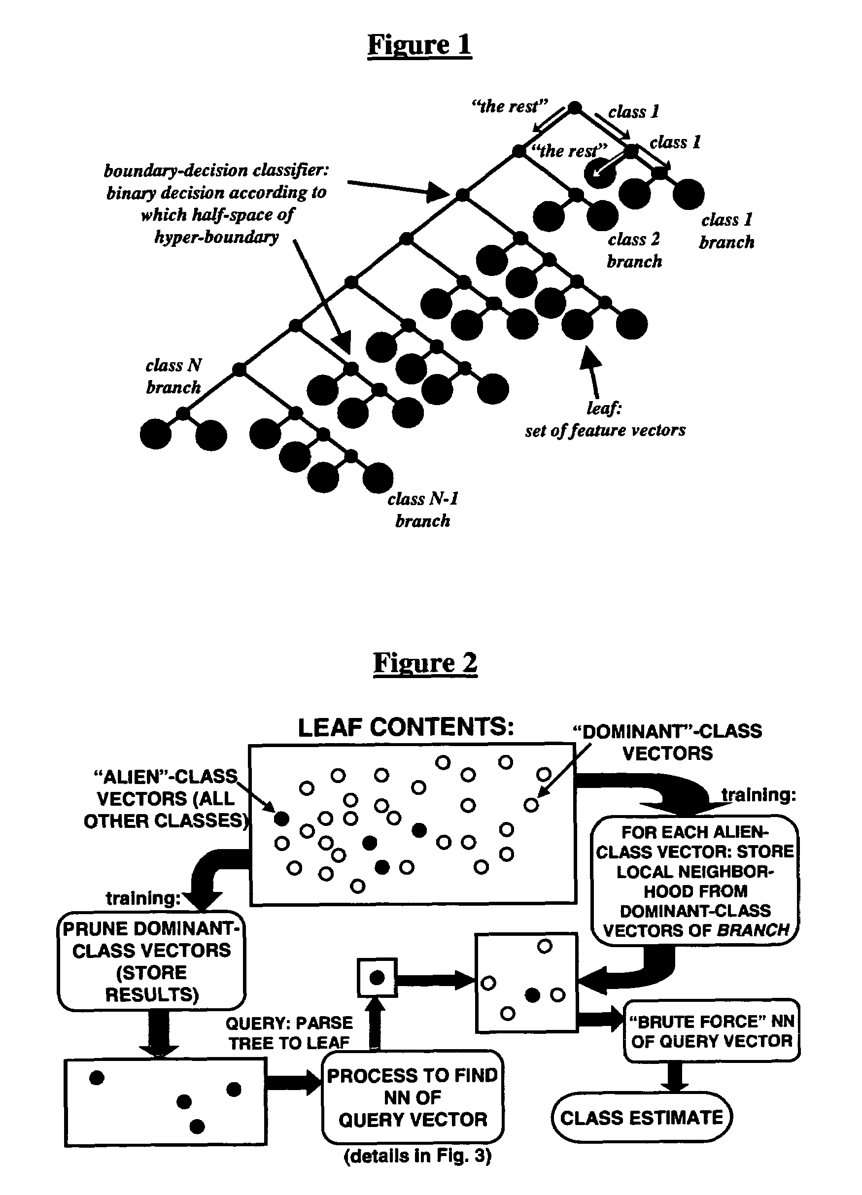
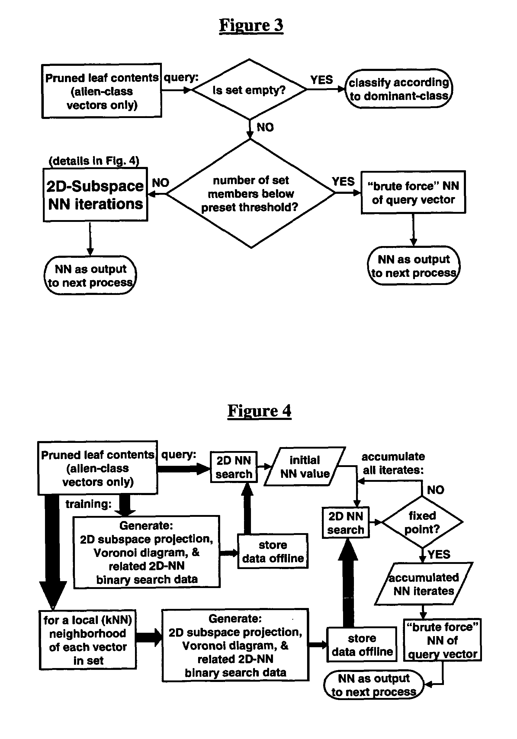
[0031]The invention provides a fusion process for the construction of new classifiers from existing low complexity boundary-decision classifiers. Generally, the inventive process fuses binary-class boundary-decision classifiers with a nove...


PUM


Abstract

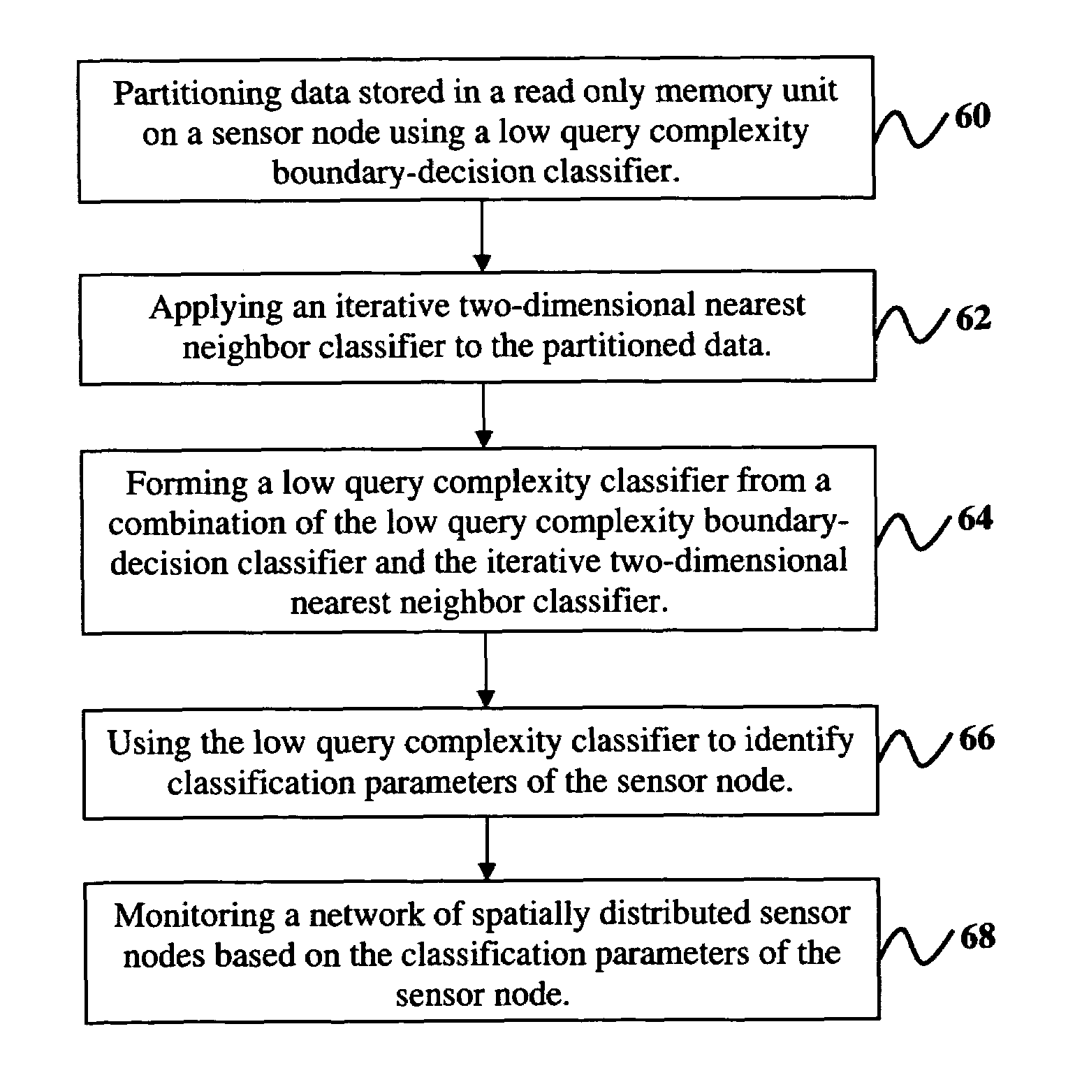
Disclosed are a system and method of multi-modality sensor data classification and fusion comprising partitioning data stored in a read only memory unit on a sensor node using a low query complexity boundary-decision classifier, applying an iterative two-dimensional nearest neighbor classifier to the partitioned data, forming a low query complexity classifier from a combination of the low query complexity boundary-decision classifier and the iterative two-dimensional nearest neighbor classifier, using the low query complexity classifier to identify classification parameters of the sensor node, and monitoring a network of spatially distributed sensor nodes based on the classification parameters of the sensor node. The boundary-decision classifier comprises a single low neuron count hidden layer and a single binary-decision output sensor node, or alternatively, the boundary-decision classifier comprises a linear classifier. Moreover, the network is a wireless unattended ground sensor network, and the data comprises signals transmitted by the sensor node.

Description

BENEFIT CLAIM[0001]This application claims the benefit of U.S. Provisional Application No. 60 / 481,479, filed Oct. 7, 2003, which is incorporated by reference herein in its entirety.GOVERNMENT INTEREST[0002]The invention described herein may be manufactured, used, and / or licensed by or for the United States Government.BACKGROUND OF THE INVENTION[0003]1. Field of the Invention[0004]The invention generally relates to sensor systems, and more particularly to systems and methods of attaining data fusion from a wireless unattended ground sensor network.[0005]2. Description of the Related Art[0006]Within this application several publications are referenced by Arabic numerals within brackets. Full citations for these, and other, publications may be found at the end of the specification immediately preceding the claims. The disclosures of all these publications in their entireties are hereby expressly incorporated by reference into the present application for the purposes of indicating the b...

Claims


Application Information

Patent Timeline
IPC IPC(8): G06E1/00G06E3/00G06F15/18G06G7/00
CPCG06K9/00979G06K9/6276G06K9/6282G06K9/6292G06V10/95G06F18/24147G06F18/24323G06F18/254
Inventor FLIPPEN, JR., LUTHER D.
Owner ARMY US SEC THE
Learn More