Solenoid valve

a solenoid valve and valve body technology, applied in the direction of valve operating means/releasing devices, functional valve types, mechanical apparatus, etc., can solve the problems of easy permanent distortion caused by compression deformation, dimensional accuracy deterioration, and high stiffness is more difficult to deform, so as to reduce manufacturing costs, improve productivity, and improve dimensional accuracy. the effect of hard to deterioration

Inactive Publication Date: 2008-03-18
KOGANEI
View PDF12 Cites 10 Cited by
  • Summary
  • Abstract
  • Description
  • Claims
  • Application Information

AI Technical Summary

Benefits of technology

[0008]Conventionally, in the rubber-made valve body provided at a tip of the plunger, its thickness dimension in an opening / closing direction of the valve body is increased so that the valve body is sufficiently elastically deformed and securely contacts with the valve seat, and the spring member is incorporated in the accommodating chamber so as to apply the spring force to the valve body in a manner as described above. However, when a diameter of the valve seat is increased to increase a flow rate of fluid or the solenoid valve is used in a pneumatic pressure pipe with high fluid pressure, large fluid pressure is applied to the plunger. For this reason, since the valve seat must be closed against such large fluid pressure, a spring member having a strong spring force is used in the solenoid valve. If such a spring member is used, permanent distortion caused by compression deformation occurs easily in the valve body formed of an elastic body such as synthetic rubber. The valve body is deformed plastically with an increase in the accumulated permanent distortion, so that its dimensional accuracy deteriorates with time.
[0009]The valve body formed by baking the elastic body such as synthetic rubber into the concave portion of the plunger with high stiffness is more difficult to deform than the case where the valve body composed of only the elastic body is incorporated into the accommodating chamber along with the spring member. However, in a conventional manufacturing method of baking the elastic body into the concave portion, productivity is low and manufacture cost is high in that respective steps of processing and cleaning the plunger and coating it with the adhesive agent are required before baking and that steps of cutting surplus portions and grinding the cut portions are required after the baking.
[0010]An object of the present invention is to provide a solenoid valve which can achieve improvement of the productivity and a reduction in the manufacture cost.
[0011]Another object of the present invention is to provide a solenoid valve which can achieve improvement of durability and stabilization of quality by using a valve body with small permanent distortion.
[0014]According to the present invention, since the poppet, the cap, and the plunger can be respectively assembled by press-insertion, the improvement of productivity and the reduction in manufacture cost can be achieved. Since these members have been assembled by press-insertion, only any worn member can be replaced and the other members can be recycled.
[0015]According to the present invention, since the valve body is baked to the supporting plate which is hard to deform, the compression permanent distortion is hard to cause, i.e., the dimensional accuracy is hard to deteriorate. Consequently, the improvement of durability and the stabilization of quality can be achieved.

Problems solved by technology

However, when a diameter of the valve seat is increased to increase a flow rate of fluid or the solenoid valve is used in a pneumatic pressure pipe with high fluid pressure, large fluid pressure is applied to the plunger.
If such a spring member is used, permanent distortion caused by compression deformation occurs easily in the valve body formed of an elastic body such as synthetic rubber.
The valve body is deformed plastically with an increase in the accumulated permanent distortion, so that its dimensional accuracy deteriorates with time.
The valve body formed by baking the elastic body such as synthetic rubber into the concave portion of the plunger with high stiffness is more difficult to deform than the case where the valve body composed of only the elastic body is incorporated into the accommodating chamber along with the spring member.
However, in a conventional manufacturing method of baking the elastic body into the concave portion, productivity is low and manufacture cost is high in that respective steps of processing and cleaning the plunger and coating it with the adhesive agent are required before baking and that steps of cutting surplus portions and grinding the cut portions are required after the baking.

Method used


Image

  • Solenoid valve
  • Solenoid valve
  • Solenoid valve

Examples


Embodiment Construction

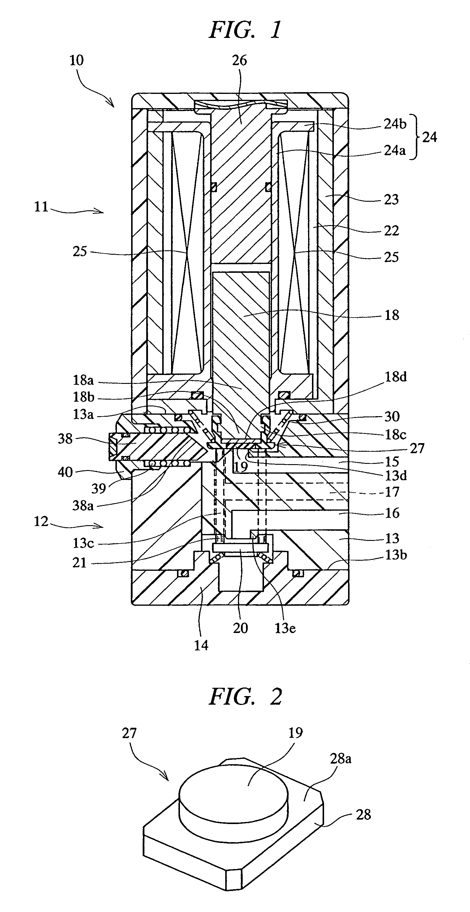
[0020]Hereinafter, embodiments of the present invention will be detailed with reference to the drawings. As shown in FIG. 1, this solenoid valve 10 comprises a solenoid housing 11 and a valve housing 12. The valve housing 12 is constituted by a substantially rectangular parallelepiped main body block 13 and an end cover 14. An upper side of the main body block 13 serves as a connecting surface 13a in which the solenoid housing 11 is incorporated, and a lower side of the main body block 13 serves as a connecting surface 13b to which the end cover 14 is assembled. Three ports 15 to 17 are opened in a side surface continuous substantially perpendicularly to the connecting surfaces 13a and 13b.

[0021]The port provided in a solenoid side of the main body block 13 is a P port in which fluid flows, that is, a supply port 15; the port provided in a side of the end cover 14 is an R port, that is, an exhaust port 16; and the port provided between the supply port 15 and the exhaust port 16 is ...


PUM


Abstract

A solenoid valve includes a poppet formed by a valve body and a supporting plate, the supporting plate having a front surface which the valve body is firmly fixed and a rear surface contacting a tip surface of a plunger. The solenoid valve further includes a cap having: a cylindrical portion which is fitted to an outer circumference of the plunger; an inward projecting portion which projects inwardly from the cylindrical portion so as to abut an outer circumferential portion of the front surface of the supporting plate; and an outward projecting portion which projects outwardly from the cylindrical portion so as to be engaged with a spring member. The poppet is press-inserted into the cap such that the inward projecting portion of the cap and the outer circumferential portion of the front surface of the supporting plate abut each other, and the cap is press-inserted into a tip portion of the plunger such that the poppet is attached on the tip surface of the plunger.

Description

TECHNICAL FIELD[0001]The present invention relates to a solenoid valve for opening / closing a flow path by controlling a current carried to a solenoid.BACKGROUND ART[0002]A directional control valve such as a control valve or a check valve is used for making air flow in an air pressure pipe, stopping its flow, and changing directions of its flow. Of the directional control valves, the valve which opens / closes the flow path by controlling the current carried to the solenoid is called a solenoid valve.[0003]The solenoid comprises a coil, a column, and a plunger, wherein when the current is carried to the coil, the plunger is attracted by the magnetized column and, in cooperation with such attraction, a main valve thereof can be shifted. A type of main valve includes a poppet type in which a valve body moves a vertical direction of its valve seat so as to open / close the flow path, a spool type in which the valve body inscribed on a cylinder moves axially so as to open / close the flow pat...

Claims


Application Information

Patent Timeline
Patent Type & Authority Patents(United States)
IPC IPC(8): F16K31/02F16K31/06
CPCF16K31/0603F16K31/0658
Inventor TSUCHIZAWA, TOSHIAKITERAKI, KOUICHI
Owner KOGANEI
Why Eureka
Try Eureka