Angioplasty stents

a technology of angioplasty and stents, which is applied in the field of stents, can solve the problems of unfavorable inner surface areas, active agents, and insufficient amount of stent coating agents, and achieve the effect of reducing the risk of infection

Inactive Publication Date: 2008-03-18
CID CO LTD
View PDF50 Cites 90 Cited by
  • Summary
  • Abstract
  • Description
  • Claims
  • Application Information

AI Technical Summary

Benefits of technology

[0012]The purpose of the present invention is to make a stent of an improved type which is able to reconcile in an optimal way the characteristics of longitudinal flexibility, which are required, for example, during the phase in which the stent is made to advance towards the implantation site, with the characteristics of plastic behavior required for the stent to be able to perform an altogether effective action of support after being expanded or dilated, minimizing and virtually eliminating any phenomena of recoil.

Problems solved by technology

First, the amount of agent with which the stent is coated may in actual fact prove insufficient, particularly when the aim is to obtain a release, and hence an action, that is prolonged in time. Further, in applications of vascular angioplasty, the surfaces of the stent, and in particular the inner surface, are subjected to an action of flushing by the blood flow.
Second, for the reason just mentioned, it is desirable that the active or activatable agent should be carried and released prevalently, if not exclusively, on the outer surface of the stent, and not on its inner surface. This is particularly true in the case where the agent applied on the stent is designed to perform an antagonistic function in regard to restenosis. In these situations, the function of the active agent, which is aimed at acting on the outer surface of the stent facing the wall of the vessel undergoing treatment may have unfavorable effects in areas corresponding to the inner surface; for example, the phenomena of neointima formation on the inner surface of the stent, which are considered to be beneficial in the phases subsequent to the implant phase, may be hindered.

Method used


Image

  • Angioplasty stents
  • Angioplasty stents
  • Angioplasty stents

Examples


example 1

[0066]Reference is made to an element 3 (see FIG. 5) having a full square section of 120×120 microns (14400 square microns), the micron (10−6 meters) constituting the typical unit of measurement to which reference is made when determining the dimensions of the component parts of a stent.

[0067]An element of this sort may be coated by means of dipping in a substance such as a polymer, which can function as a carrier of active agents.

[0068]Tests currently carried out show that the maximum thickness of substance that can be deposited and withheld on the element 3 is in the region of 20 microns.

[0069]This means that the layer of substance facing the outside of the stent and able to perform an effective action has a sectional area of approximately 2400 square microns.

example 2

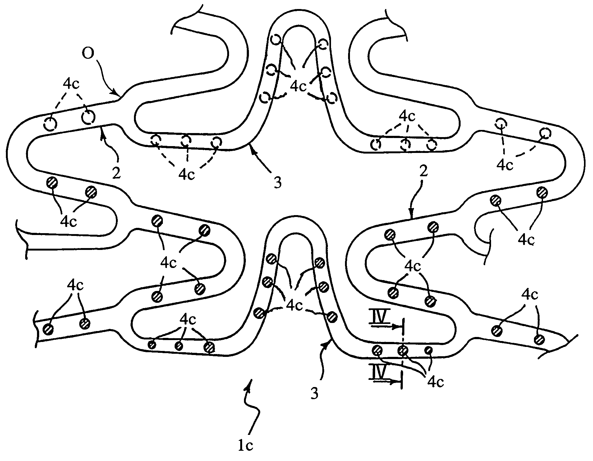
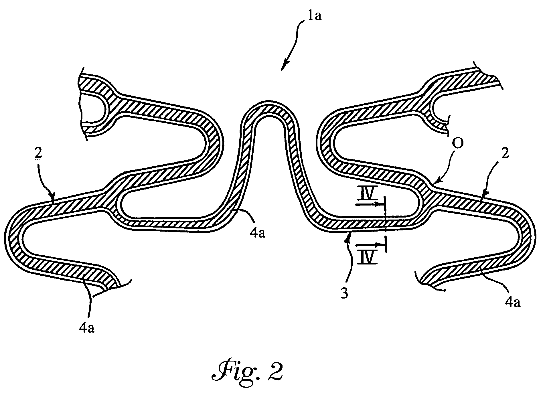
[0070]In an element 3 having the dimensional characteristics of the full element of Example 1, a continuous recess 4 was formed by means of laser etching according to the general geometry represented in FIG. 5. The recess had a depth (measured in the radial direction with respect to the stent) of 60 microns and a width (measured in the direction tangential to the stent) of 40 microns.

[0071]The recess thus occupied a portion corresponding to approximately 17% of the overall sectional area of the element and was able to receive inside it the same quantity of active substance as in Example 1 (sectional area corresponding to approximately 2400 square microns).

[0072]The bending moments of inertia Ix and Iy of the element 3 provided with the recess, determined, respectively with reference to:

[0073]An X axis oriented in a direction that is transverse and tangential with respect to the stent and a Y axis oriented in a direction that is radial with respect to the stent, were found to be equa...

example 3

[0074]A recess having the same sectional area as the recess of example 2 was made in an element 3, the external dimensions of which were increased to 140 microns in height (measured in the radial direction with respect to the stent) and 120 microns in width (measured in the direction orthogonal to the height), so as to have an area of metal section, and hence characteristics of resistance to longitudinal stresses, corresponding to those of the element 3 of Example 1 (14400 square microns). In this case, the recess occupied a portion corresponding to approximately 14% of the overall sectional area of the element.

[0075]The moments of inertia Ix and Iy, determined according to the same modalities seen previously, were, respectively 116% and 112% of the homologous moments of inertia of the element of Example 1.


PUM


Abstract

A stent for use at an implant site in a vessel having recesses containing one or more active agents. The stent is a tubular body having a plurality of sinusoidal shaped annular elements and connection elements. The recesses are formed so as to leave substantially unaltered the bending moments of these elements. The recesses may be continuous or discontinuous and may be distributed uniformly or nonuniformly.

Description

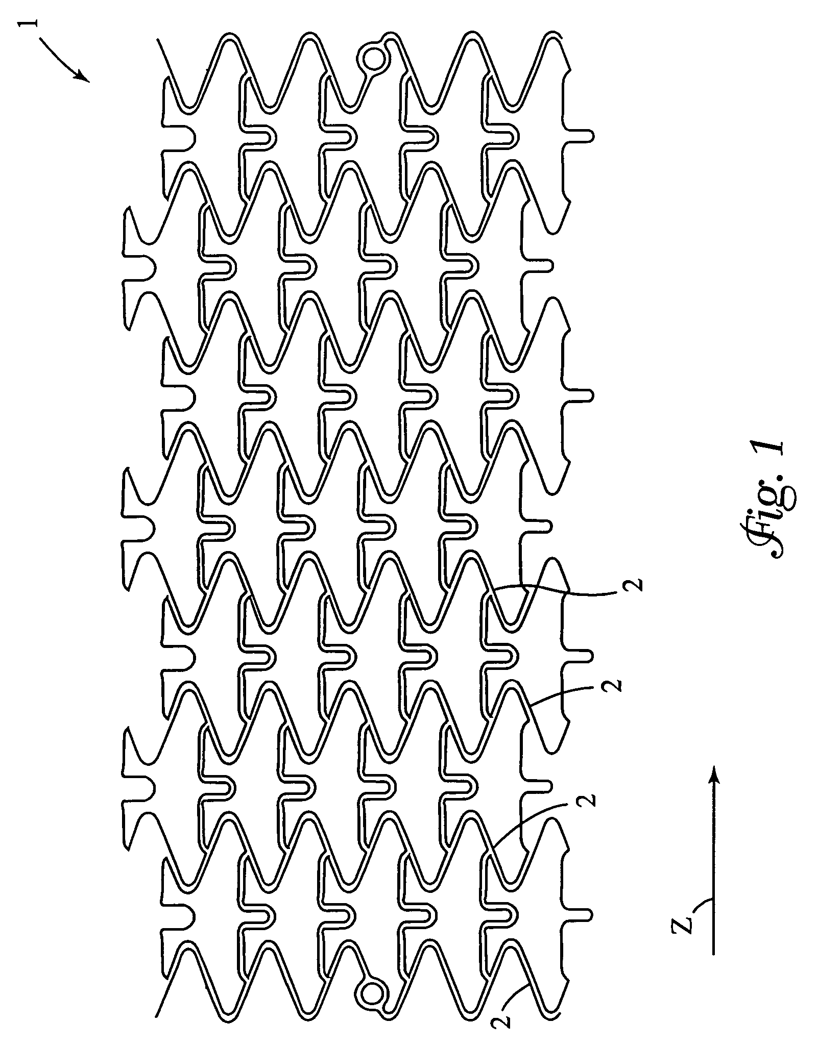
[0001]This application is a continuation of U.S. Ser. No. 10 / 198,054, filed Jul. 18, 2002, now U.S. Pat. No. 6,699,281, the contents of which are hereby incorporated by reference herein.FIELD OF THE INVENTION[0002]The present invention relates to stents, and in particular, relates to angioplasty stents adapted to convey therapeutic agents.BACKGROUND OF THE INVENTION[0003]The term “stent” is intended to indicate devices intended for endoluminal application (e.g. within a blood vessel), normally fitted via catheterization, with subsequent deployment in situ so as to provide a local supporting effect for the lumen. Stents are extensively disclosed in the patent literature, for example co-pending, commonly assigned EP 0 806 190, EP 0 850 604, EP 0 857 470, EP 0 875 215, EP 0 895 759, EP 0 895 760, EP 1 080 738, EP 1 088 528, and EP 1 103 234.[0004]In particular, the present invention falls within the line of research aimed at developing solutions that enable the stent to be used as a ve...

Claims


Application Information

Patent Timeline
Patent Type & Authority Patents(United States)
IPC IPC(8): A61F2/06A61F2/00A61F2/91A61F2/915
CPCA61F2/91A61F2/915A61F2002/91541A61F2230/0054A61F2002/91583A61F2250/0068A61F2002/9155
Inventor VALLANA, FRANCOROLANDO, GIOVANNICURCIO, MARIAGASCHINO, PAOLO
Owner CID CO LTD
Why Eureka
Try Eureka