Traffic line recognition device

a recognition device and traffic line technology, applied in the field can solve the problems of traffic line recognition devices employing, needing a processing unit of high performance, increasing the cost of devices, etc., and achieve the effect of large amount of resources and high performan

Active Publication Date: 2008-03-18
MITSUBISHI ELECTRIC CORP
View PDF6 Cites 39 Cited by
  • Summary
  • Abstract
  • Description
  • Claims
  • Application Information

AI Technical Summary

Benefits of technology

[0007]The present invention has been made to solve the above described problems. The object of the present invention is to realize a traffic line recognition device capable of responding to different kinds of traffic lines such as ordinary white lines and Botts' dots without requiring a processing unit of high performance and a large amount of resources.
[0009]The traffic line recognition device of the present invention is so constructed as to convert pixels included in the traffic line region candidate into three dimensional coordinates and to produce a histogram acquired by accumulating and projecting the three dimensional coordinates to the coordinate system in the direction crossing the road and to determine a traffic line on the basis of the value of this histogram. Therefore, this can provide a device capable of recognizing a traffic line even in a road having different kinds of traffic lines such as white lines and Botts' dots without requiring a processing unit of high performance and a large amount of resources.

Problems solved by technology

However, among the conventional traffic line recognition devices, a traffic line recognition device using the Hough transformation needs a processing unit of high performance because of heavy processing load.
Hence, the device by this method causes a problem of increasing the cost of device.
On the other hand, a traffic line recognition device employing different methods for the white line and the Botts' dots needs a large amount of resources such as memory.
Hence, the device employing such methods also is not a desirable one as a device mounted on a vehicle.

Method used


Image

  • Traffic line recognition device
  • Traffic line recognition device
  • Traffic line recognition device

Examples


embodiment 1

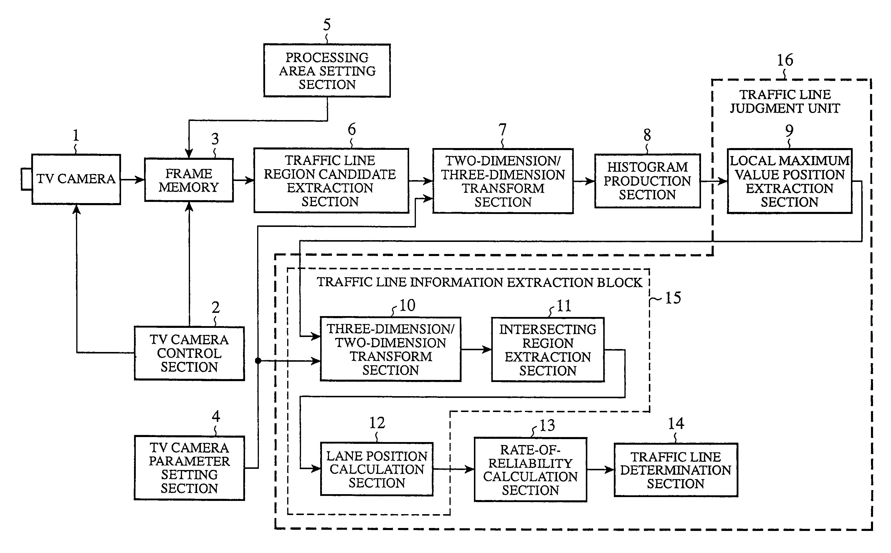
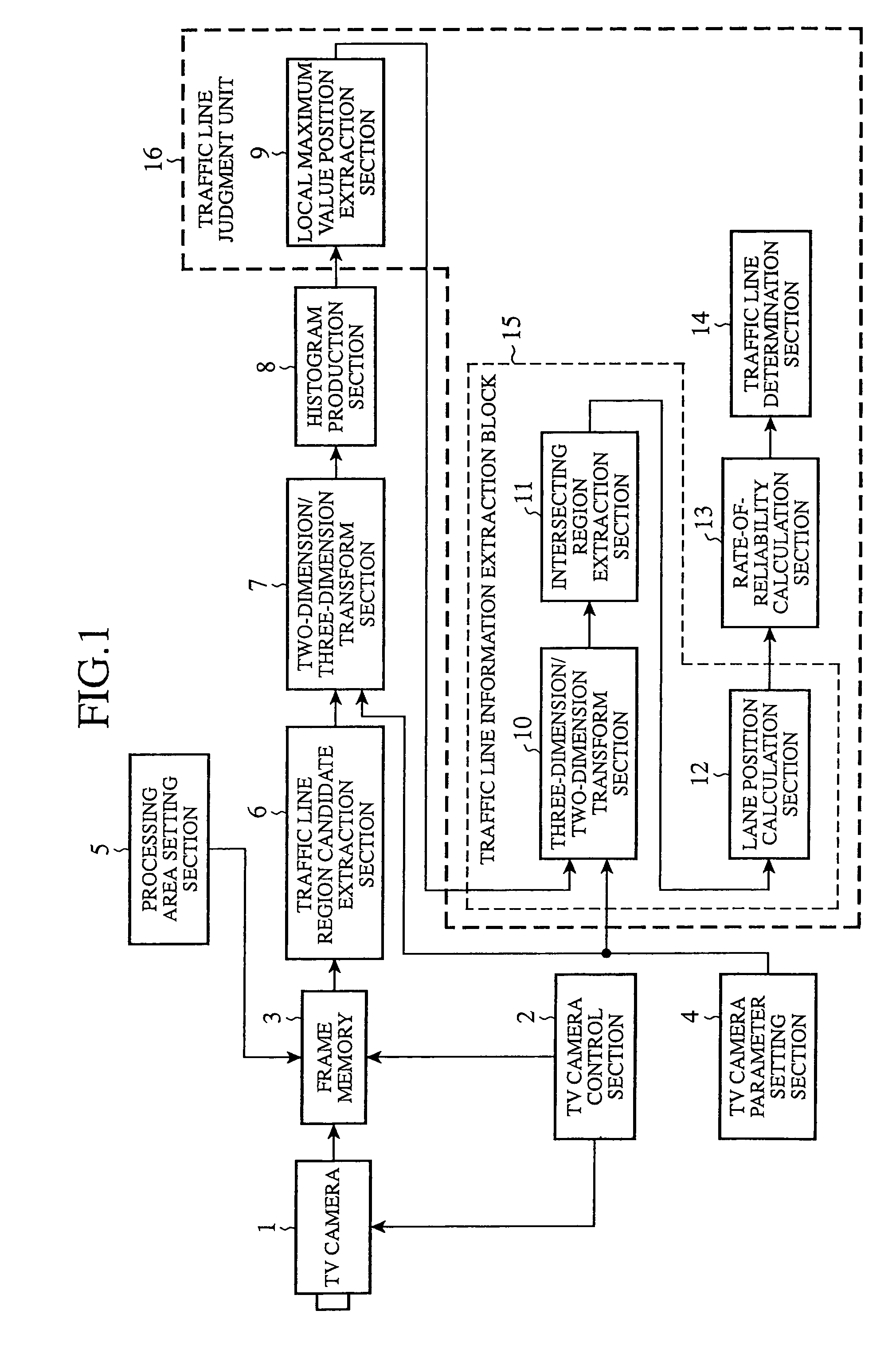
[0019]FIG. 1 is a block diagram to show a traffic line recognition device in accordance with embodiment 1 of the present invention.

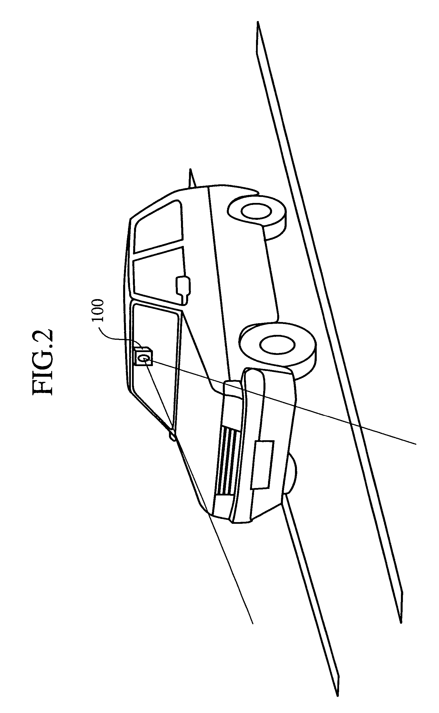
[0020]FIG. 2 is an illustration to show a state where the traffic line recognition device in accordance with embodiment 1 of the present invention is mounted.

[0021]In these drawings, a traffic line recognition device 100 includes a TV camera 1, a TV camera control section 2, a frame memory 3, a TV camera parameter setting section 4, a processing area setting section 5, a traffic line region candidate extraction section 6, a two dimensions / three dimensions transform section 7, a histogram production section 8, a local maximum value position extraction section 9, a three dimensions / two dimensions transform section 10, an intersection region extraction section 11, a traffic line position calculation section 12, a rate of reliability calculation section 13, and a traffic line determination section 14. At this point, a traffic line information extraction bloc...


PUM


Abstract

A traffic line recognition device includes: a traffic line region candidate extraction section that extracts a traffic line candidate, as a traffic line candidate, from a road image obtained by a TV camera installed on a vehicle; a two dimension / three dimension transform section that transforms two dimensional image coordinates of a pixel contained in the traffic line region candidate into three dimensional coordinates; a histogram production section that accumulates and projects the three dimensional coordinates onto a coordinate system in a direction crossing a road and produces a histogram in the direction crossing the road; and a traffic line judgment unit determines a traffic line based on that histogram.

Description

BACKGROUND OF THE INVENTION[0001]1. Field of the Invention[0002]The present invention relates to a traffic line recognition device for recognizing traffic lines between which a vehicle runs.[0003]2. Description of the Related Art[0004]In a conventional traffic line recognition device, for example, as disclosed in a patent document 1, a Hough transformation has been used at the time of finding a white line on a road. Moreover, in addition to a method of using such a Hough transformation, for example, as disclosed in a patent document 2, in order to respond to different kinds of traffic lines such as ordinary white line and traffic line made by Botts' dots, there has been proposed a traffic line recognition device using different processing methods for the respective different kinds of traffic lines.[Patent document 1] Japanese Unexamined Patent Publication No. 11-85999[Patent document 1] Japanese Unexamined Patent Publication No. 2003-123058[0005]However, among the conventional traff...

Claims


Application Information

Patent Timeline
Patent Type & Authority Patents(United States)
IPC IPC(8): G06K9/00H04N7/00B60R21/00G06T1/00G06T7/00G06T7/60G08G1/16
CPCG06K9/00798G06V20/588
Inventor TANIGUCHI, HIROYASUHASHIMOTO, MANABU
Owner MITSUBISHI ELECTRIC CORP
Why Eureka
Try Eureka