Method for RF fingerprinting

a fingerprinting and mobile technology, applied in the field of mobile unit location, can solve the problems of insufficient sensitivity of the measuring device to distinguish, and limited resolution

Inactive Publication Date: 2008-03-18
INNERWIRELESS
View PDF46 Cites 327 Cited by
  • Summary
  • Abstract
  • Description
  • Claims
  • Application Information

AI Technical Summary

Benefits of technology

[0022]It is an object of the present invention to prepare a physical environment for location determination of a mobile unit in such a way that will increase the accuracy of reference fingerprints used to provide location estimates for a mobile unit.
[0023]It is a further object of the invention to accurately report the location of a mobile unit in a wireless environment.

Problems solved by technology

Of course, a person skilled in the art can appreciate that the resolution is limited by the sensitivity of the fingerprint measuring device.
In addition, if two fingerprints for different locations look too much alike (e.g., due to insufficient sensitivity in the measuring device), then accuracy is lessened.
This can happen because the sensitivity of the measuring device is insufficient to distinguish between the RF fingerprints at the locations.
It can also happen because the RSSI data at one or more of the locations is relatively unstable.
This means that the signal strength changes in unpredictable ways (e.g., a signal strength that is often + / −4 dBm different than recorded in the RF fingerprint).
The prior art does not address unpredictable variation, as opposed to predictable variation, such as a transmitter that powers down at the same time every day.
Another cause for an RF environment to be ambiguous relates to the placement of transmitters which can result in aliasing problems.
This introduces two new problems to basic RF fingerprinting techniques.
First, when gathering data to generate an RF fingerprint, signals may not be observable from all transmitters used in generating the fingerprint.
The second problem related to producing frequent location estimates is that producing a new location estimate each time a new RF fingerprint is generated can result in a jittery series of estimates.

Method used


Image

  • Method for RF fingerprinting
  • Method for RF fingerprinting
  • Method for RF fingerprinting

Examples


Embodiment Construction

[0034]The claimed invention is directed to location of mobile units in a wireless environment and to preparing a physical environment for location of a mobile unit. The preparation of the physical environment is referred to herein as the survey process, while the actual location of the mobile unit in the physical environment is referred to as the run-time process. In each of these processes, the claimed invention provides techniques. Some techniques are particular to the survey process, while others are particular to the run-time process, while still other techniques are relevant to both the survey process and the run-time process.

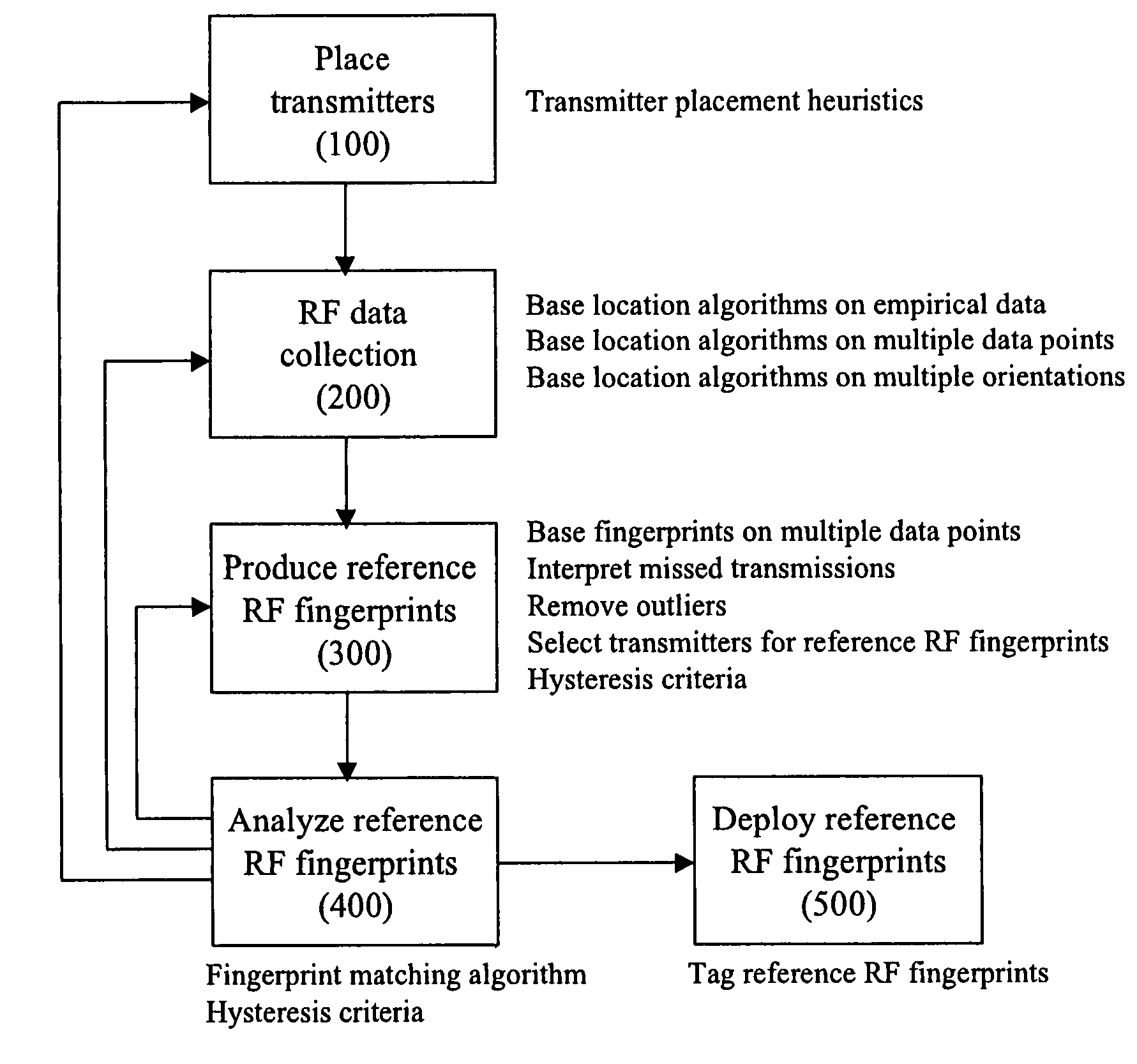
[0035]A high-level overview of the survey process used to prepare a physical environment for location determination is shown in FIG. 4. Each step is annotated with the techniques that are applied during that step in the survey process.

[0036]As shown in FIG. 4, the first step is to place transmitters 100. Typically when placing transmitters to wirelessly en...


PUM


Abstract

The invention provides a novel method for preparing a wireless environment for location determination of a wireless mobile unit, and for location determination of a wireless mobile unit. In preparing the physical environment, the invention utilizes novel techniques, including novel techniques to place transmitters, the removal of outlying data in the creation of reference RF fingerprints, and algorithms to obtain accurate reference RF fingerprints. In determining the location of a wireless mobile unit, the invention utilizes novel techniques, including novel techniques to select transmitters, the removal of outlying data in the creation of reference RF fingerprints, and algorithms to obtain accurate reference RF fingerprints.

Description

CLAIM OF PRIORITY[0001]Pursuant to 35 U.S.C. 119(e), this application claims the benefit of U.S. Provisional Application No. 60 / 491,379 filed Jul. 31, 2003.FIELD OF THE INVENTION[0002]The claimed invention relates to location of mobile units in a wireless environment. Further, the claimed invention is a method for preparing a physical environment for location of a mobile unit.BACKGROUND OF THE INVENTION[0003]RF fingerprinting is a method for locating the position of a mobile unit (MU) in a wireless communication network. RF fingerprinting is described generally in U.S. Pat. No. 6,269,246.[0004]RF fingerprinting is particularly useful in indoor settings where technologies such as GPS are typically not reliable. It works with information already available in indoor settings, such as the received signal strength indicator (RSSI or signal strength) obtainable from an IEEE 802.11 network installed to provide wireless connectivity, and does not require any additional hardware. As such, RF...

Claims


Application Information

Patent Timeline
Patent Type & Authority Patents(United States)
IPC IPC(8): H04Q7/20G01S19/46G01S5/02H04W64/00
CPCG01S5/0252H04W64/00G01S5/02526
Inventor DAMARLA, CHANAKYAIVERS, JAMESPOLLARD, MARKKOMPANEK, ANDREW J.TRAMMELL, BRIAN H.
Owner INNERWIRELESS
Why Eureka
Try Eureka