Light emitting diode (LED) based street light and other lighting applications

a technology of light-emitting diodes and street lights, applied in the direction of photosensitive materials, coupling device connections, instruments, etc., can solve the problems of not being able to meet the needs of replacement, wasting a large amount of light from the hid lamp, and exhibiting a non-favorable spectrum at nigh

Inactive Publication Date: 2008-03-25
LEOTEK ELECTRONICS
View PDF3 Cites 101 Cited by
  • Summary
  • Abstract
  • Description
  • Claims
  • Application Information

AI Technical Summary

Benefits of technology

[0007]The present invention solves the aforementioned problems by providing an LED lamp module that does not require the LED light engine to attach to a housing via full rotation.

Problems solved by technology

Major disadvantages of using these lamps, however, are 1) they need to be replaced often due to the shorter lifespan of the lamp; 2) part of the light from the HID lamp is wasted because it is aimed in directions not useful to the original lighting purpose; 3) some of them contain hazardous material; and 4) they exhibit a non-favorable spectrum at night.
Current LED retrofitting mechanisms are also limited.
However, physical constraints of the housing sometimes do not allow for LED light engines to fully rotate.

Method used


Image

  • Light emitting diode (LED) based street light and other lighting applications
  • Light emitting diode (LED) based street light and other lighting applications
  • Light emitting diode (LED) based street light and other lighting applications

Examples


Embodiment Construction

[0025]The present invention is an LED lamp module utilizing high power LEDs that is ideal for installation in conventional traffic signal lamps. Moreover, the present invention provides an improved connection mechanism for installing a retrofit LED lamp engine in a housing which physically restricts full rotation of an LED light engine.

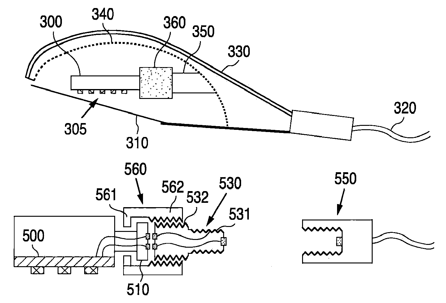
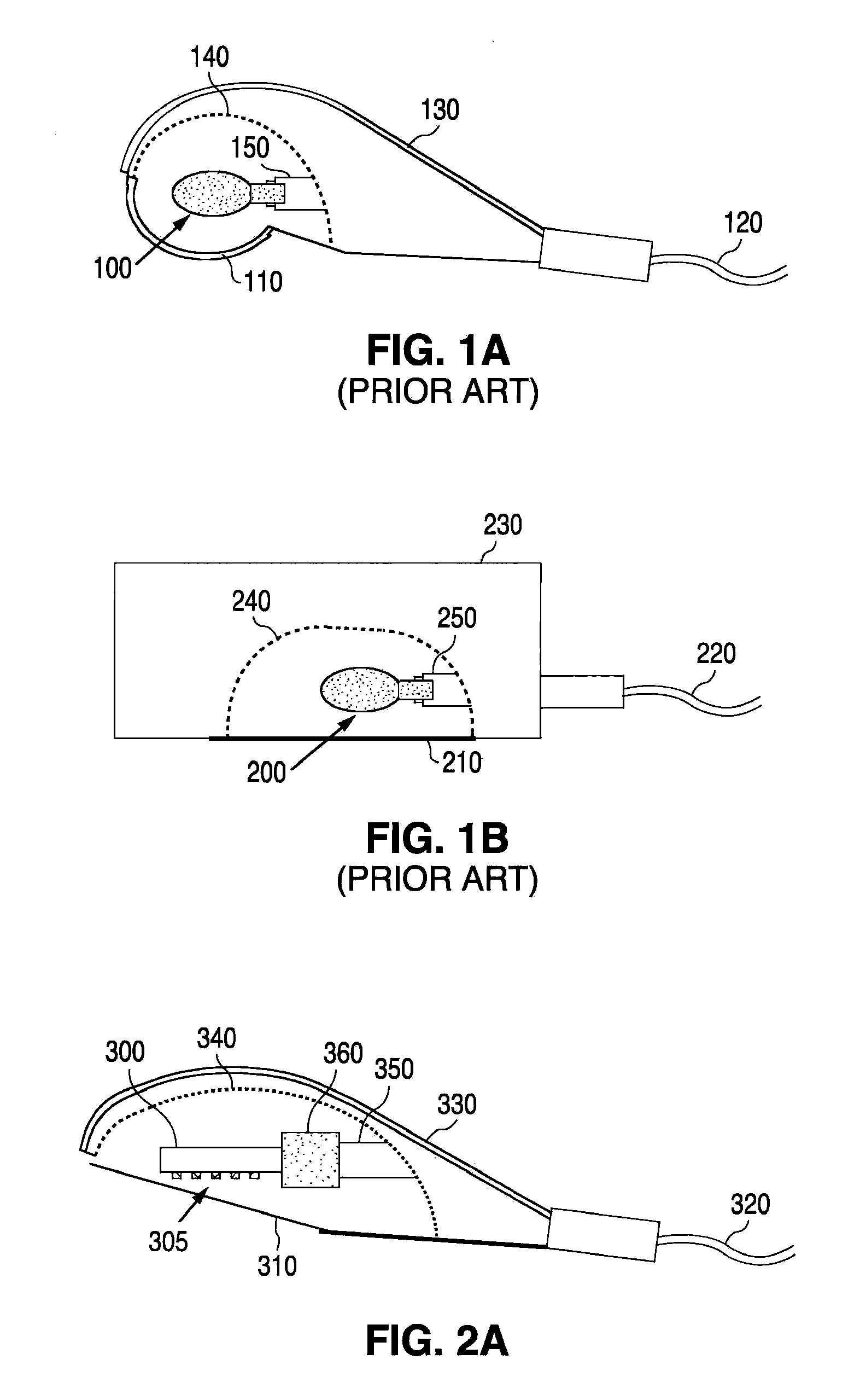
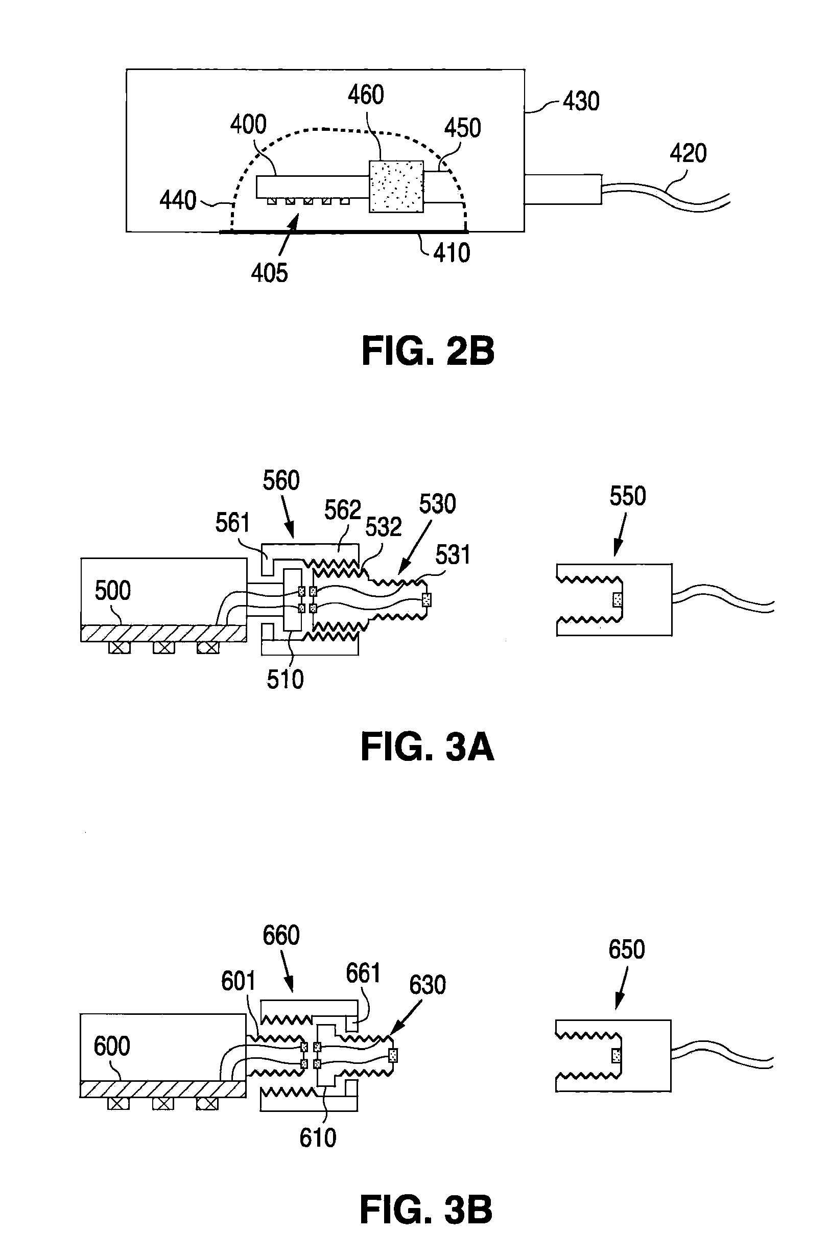
[0026]In FIG. 2a, a schematic of an LED retrofitted cobrahead luminaire in accordance with the present invention is provided. As illustrated, such a cobrahead luminaire comprises an LED light engine 300, an LED array 305, a lens 310, incoming AC lines 320, a cobra housing 330, a reflector 340, and a lamp socket 350. In FIG. 2b, a schematic of an LED retrofitted shoebox luminaire is also provided. Within this embodiment, the shoebox luminaire comprises an LED light engine 400, an LED array 405, a lens 410, incoming AC lines 420, a shoebox housing 430, a reflector 440, and a lamp socket 450. Details of connection mechanisms in accordance with the presen...


PUM


Abstract

An LED lamp module for use with a threaded electrical socket connector is provided, which includes an LED light engine with a first electrical connector, a second electrical connector having a first end electrically engagable with the first electrical connector and a second end having a threaded outer surface compatible with a threaded electrical socket connector. The LED lamp module further comprises a sleeve surrounding the first electrical connector and the first end such that the sleeve allows for relative rotation between the first electrical connector and the first end in a loosened state, and restricts relative rotation between the first electrical connector and the first end in a tightened state. A method for installing a retrofit LED lamp module in a housing which physically restricts full rotation of an LED light engine is also provided. The method includes connecting a first electrical connector to a second electrical connector, wherein the first electrical connector is attached to an LED light engine, and wherein the second electrical connector further comprises a first end electrically engagable with the first electrical connector, and a second end having a threaded outer surface compatible with a threaded electrical socket connector. The method further comprises tightening this connection via a sleeve surrounding the first electrical connector and the first end such that the sleeve allows for relative rotation between the first electrical connector and the first end in a loosened state, and restricts relative rotation between the first electrical connector and the first end in a tightened state.

Description

[0001]This application claims the benefit of U.S. Provisional Application No. 60 / 701,825, filed Jul. 21, 2005, and entitled Light Emitting Diode (LED) Based Street Light and Other Lighting Applications.FIELD OF THE INVENTION[0002]The present invention relates to the design and the installation of retrofit Light Emitting Diode (LED) modules to replace existing light sources including street lights, parking lot lights, and various other lighting applications. More particularly, the present invention relates to a method for installing a retrofit LED lamp module in a housing which physically restricts full rotation of an LED light engine.BACKGROUND OF THE INVENTION[0003]Light Emitting Diodes (LEDs) have been used in many applications to replace conventional incandescent lamps, fluorescent lamps, neon tube and fiber optics light sources in order to reduce costs and to increase reliability. Due to the fact that LEDs consume less electrical energy than most conventional light sources, whil...

Claims


Application Information

Patent Timeline
Patent Type & Authority Patents(United States)
IPC IPC(8): H01R13/62
CPCH01R13/7175H01R12/7076G06Q40/00F21V19/0065F21K9/58F21K9/13Y02B20/383F21Y2105/001Y02B20/72F21S8/08F21Y2101/02F21W2131/103F21Y2105/10F21K9/23F21K9/65F21Y2115/10Y02B20/30
Inventor WU, CHEN-HOTU, CHIN-WANGWANG, SHIH CHANG
Owner LEOTEK ELECTRONICS
Why Eureka
Try Eureka