Rotor for a wind energy turbine

a technology of wind energy turbine and rotor, which is applied in the direction of generator/motor, machine/engine, electric generator control, etc., can solve the problem of not being able to provide electrical energy to the sensors via cables

Active Publication Date: 2008-03-25
GE INFRASTRUCTURE TECH INT LLC
View PDF13 Cites 26 Cited by
  • Summary
  • Abstract
  • Description
  • Claims
  • Application Information

AI Technical Summary

Problems solved by technology

Providing electrical energy to the sensors via cables is not desirable because the cables are disadvantageous with respect to lightning strikes or the like.

Method used


Image

  • Rotor for a wind energy turbine
  • Rotor for a wind energy turbine
  • Rotor for a wind energy turbine

Examples


Embodiment Construction

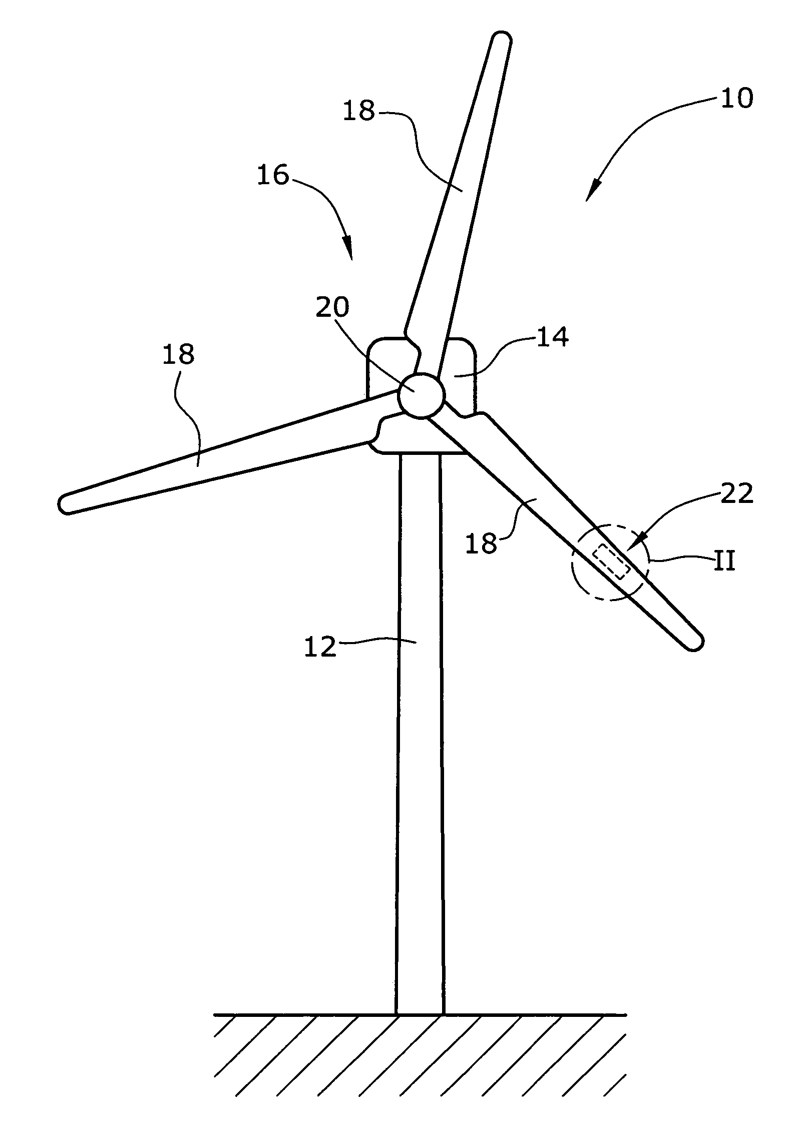
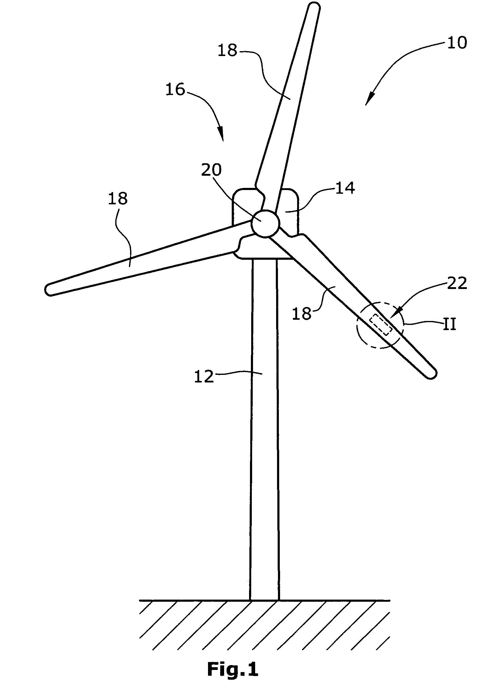
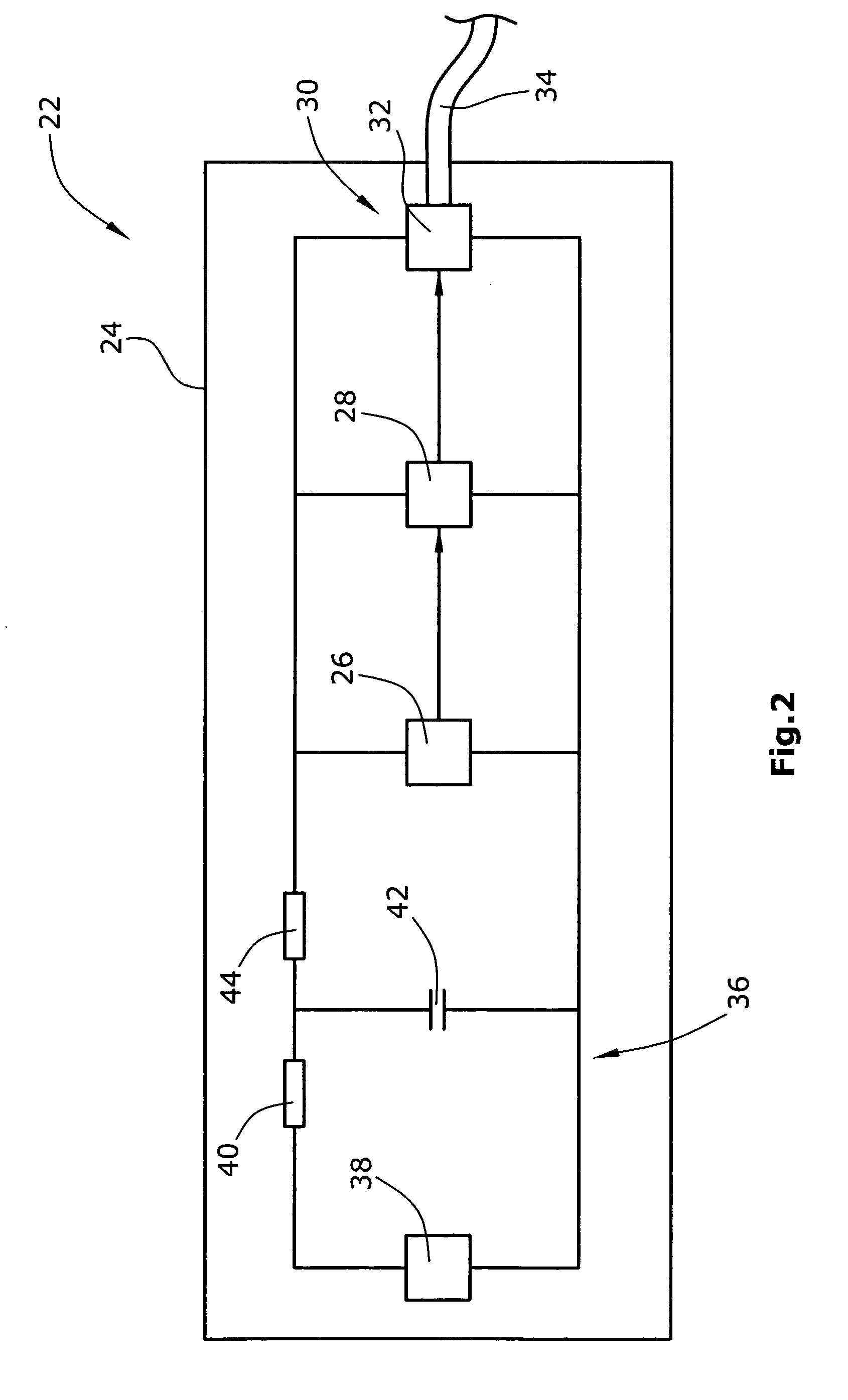
[0007]One embodiment of the present invention uses the vibrations of the rotor of the wind energy turbine and, in particular, of the blades of the rotor for converting the mechanical energy, such as the vibrations, into electrical energy. Accordingly, a rotor of a wind energy turbine includes an electromechanical converter which can be e.g. an electromagnetic or piezoelectric vibration converter for converting mechanical energy from the vibrations of the rotor when subjected to wind loads into electrical energy to be supplied to at least one sensor which senses at least one physical value of the rotor, e.g. mechanical stress or the like acting on the rotor blade. This autonomous electrical energy supply eliminates the need for power supply cables in the rotor. Electromechanical converters for converting mechanical energy into electrical energy are known in the art. Typically, those converters are designed as MEMS (Micro Electrical Mechanical Systems) and are made using semiconductor...


PUM


Abstract

A the rotor for a wind energy turbine includes a hub and at least one rotor blade connected to the hub. The rotor also includes comprises at least one sensor for sensing at least one physical value of the rotor, e.g. mechanical stress, and a power supply for supplying electrical power to the at least one sensor. The power supply includes an electromechanical converter for converting mechanical energy from vibrations of the rotor when subjected to wind loads, e.g. during operation of the wind energy turbine, into electrical energy for supplying to the at least one sensor.

Description

BACKGROUND OF THE INVENTION[0001]The present invention relates to a rotor for a wind energy turbine and, more specifically, to an autonomous power supply for at least one sensor located at the rotor for sensing at least one physical value of the rotor as well as a method for autonomously supplying electrical energy to at least one sensor arranged at the rotor of a wind energy turbine for sensing at least one physical value of the rotor.[0002]Modern wind energy turbines are provided with a plurality of different sensors for observing the current physical properties and characteristics of the wind energy turbine during its operation. Some of the sensors are arranged on the blades of the rotor of the wind energy turbine, e.g. for measuring the physical stress the rotor blade is subjected to. In order to supply the sensors with electrical energy, provision of corresponding cables is necessary. Also for transmitting the sensed data or measurement values, additional cables are necessary. ...

Claims


Application Information

Patent Timeline
Patent Type & Authority Patents(United States)
IPC IPC(8): F03D9/00
CPCF03D11/00F03D11/0091F03G7/08F05B2220/709F05B2260/80F05B2270/80F05B2270/804H02N2/186Y02E10/721Y02E10/722Y02E10/726F03D17/00Y02E10/72
Inventor RIESBERG, ANDRE
Owner GE INFRASTRUCTURE TECH INT LLC
Why Eureka
Try Eureka