Algorithms and methods for determining laser beam process direction position errors from data stored on a printhead

a laser beam and printhead technology, applied in the field of electrotrophotographic imaging apparatus, can solve the problems of increasing the precision required by each optical element, introducing process direction errors, and skewing associated with printed images

Active Publication Date: 2008-03-25
LEXMARK INT INC
View PDF49 Cites 39 Cited by
  • Summary
  • Abstract
  • Description
  • Claims
  • Application Information

AI Technical Summary

Problems solved by technology

Unavoidable imprecision in the shape and mounting of these optical elements with respect to the laser beam and / or drum can introduce process direction errors in the path of travel of the laser beam when writing across a scan line.
Under these conditions, there may be a skew associated with the printed image.
However, the increased precision required by each optical element adds significantly to its cost.
Even with precisely manufactured and aligned optics, the degree to which laser beam process direction position errors may be corrected is limited by several factors, including component tolerances.
Moreover, distortion of the laser beam optical scan path can occur even in a precisely aligned system due to component aging and / or operational influences such as temperature changes.

Method used


Image

  • Algorithms and methods for determining laser beam process direction position errors from data stored on a printhead
  • Algorithms and methods for determining laser beam process direction position errors from data stored on a printhead
  • Algorithms and methods for determining laser beam process direction position errors from data stored on a printhead

Examples


Embodiment Construction

[0021]In the following detailed description of the preferred embodiments, reference is made to the accompanying drawings that form a part hereof, and in which is shown by way of illustration, and not by way of limitation, specific preferred embodiments in which the invention may be practiced. It is to be understood that other embodiments may be utilized and that changes may be made without departing from the spirit and scope of the present invention.

General System Overview

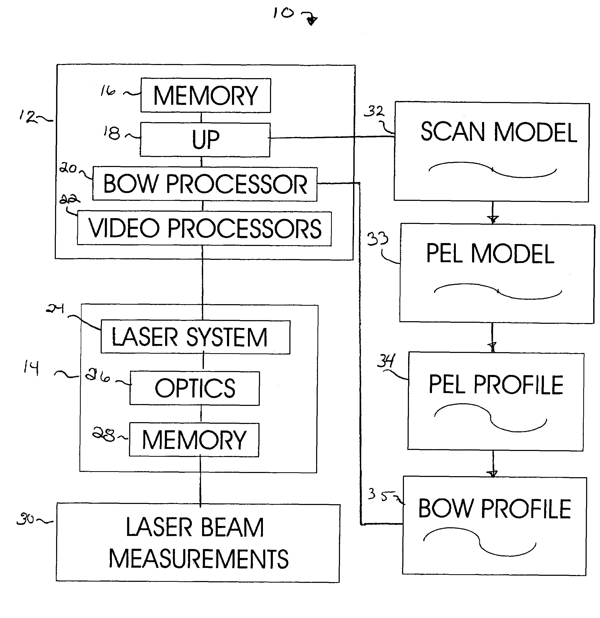
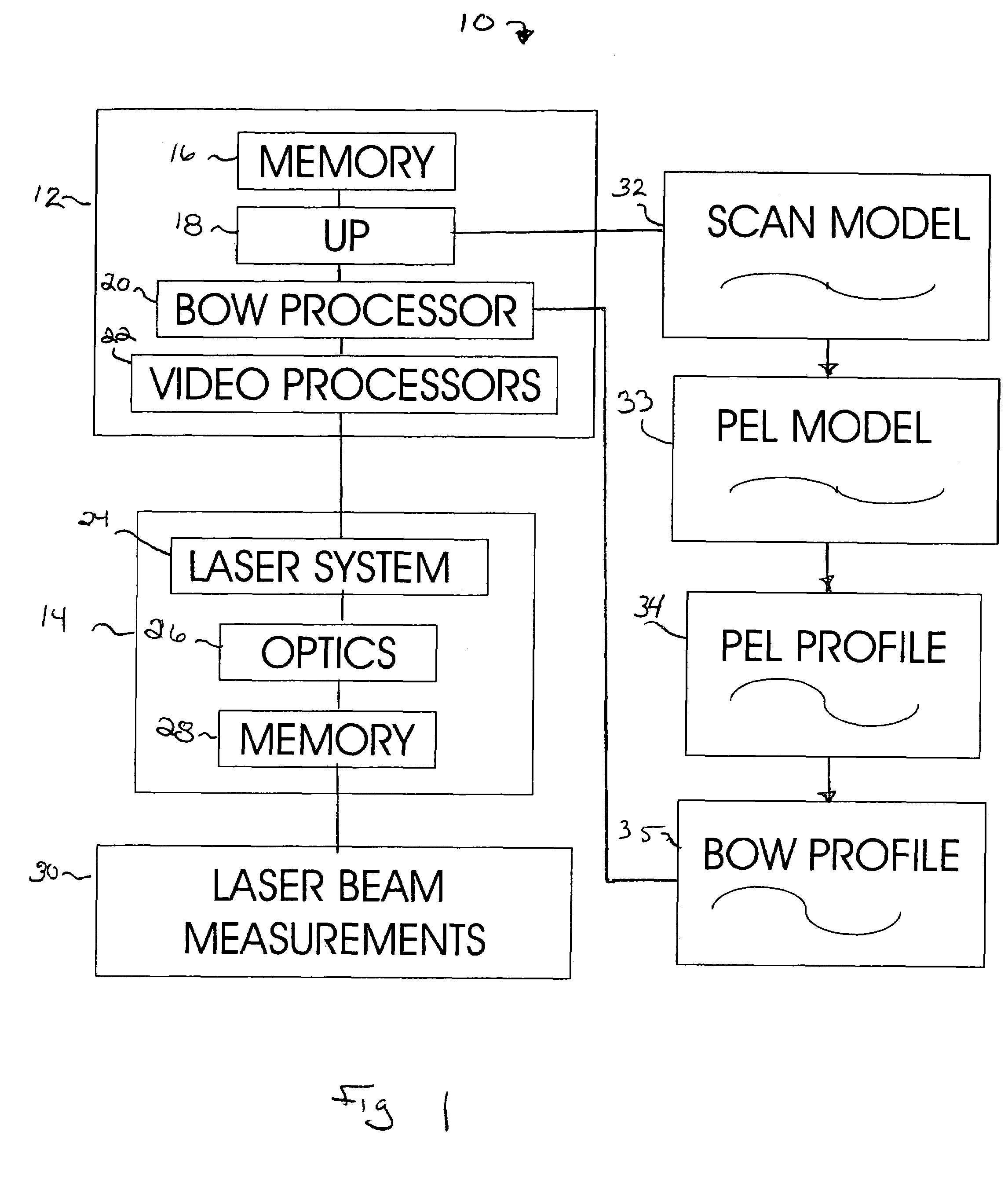
[0022]FIG. 1 illustrates the main components of a system 10 for characterizing and correcting laser beam process direction position errors according to the present invention. The system 10 includes generally, a controller 12 and a printhead 14. The controller 12 includes the electronics and logic necessary for performing electrophotographic imaging including the performance of operations necessary to characterize laser beam process direction position errors as set out in greater detail herein. As shown, the control...


PUM


Abstract

Systems and methods are provided for characterizing laser beam process direction position errors in an electrophotographic device. Once the process direction position errors of a given beam laser beam system have been characterized, an image is adjusted or warped prior to being processed by the laser beam system to compensate for laser beam process direction position errors, e.g., bow and skew.

Description

CROSS REFERENCE TO RELATED APPLICATIONS[0001]The present application is related to U.S. Pat. No. 7,206,012, entitled “Memory Device On Optical Scanner And Apparatus And Method For Storing Characterizing Information On The Memory Device”; U.S. Pat. Pub. No. 2005-0212905, entitled “Systems For Performing Laser Beam Linearity Correction And Algorithms And Methods For Generating Linearity Correction Tables From Data Stored In An Optical Scanner”; and U.S. Pat. Pub. No. 2005-0212903, entitled “Electronic Systems And Methods For Reducing Laser Beam Process Direction Position Errors”; each of which is filed currently herewith and hereby incorporated by reference herein.BACKGROUND OF THE INVENTION[0002]The present invention relates to an electrophotographic imaging apparatus, and more particularly to systems and methods for characterizing laser beam process direction position errors.[0003]In electrophotography, a latent image is created on the surface of an electrostatically charged photoco...

Claims


Application Information

Patent Timeline
Patent Type & Authority Patents(United States)
IPC IPC(8): H04N1/40B41J2/47G02B26/08G02B27/00
CPCB41J2/471G02B27/0031
Inventor CLARKE, CYRUS B.FIELDS, THOMAS A.JOHNSON, ALLEN P.JONES, CHRISTOPHER D.
Owner LEXMARK INT INC
Why Eureka
Try Eureka