

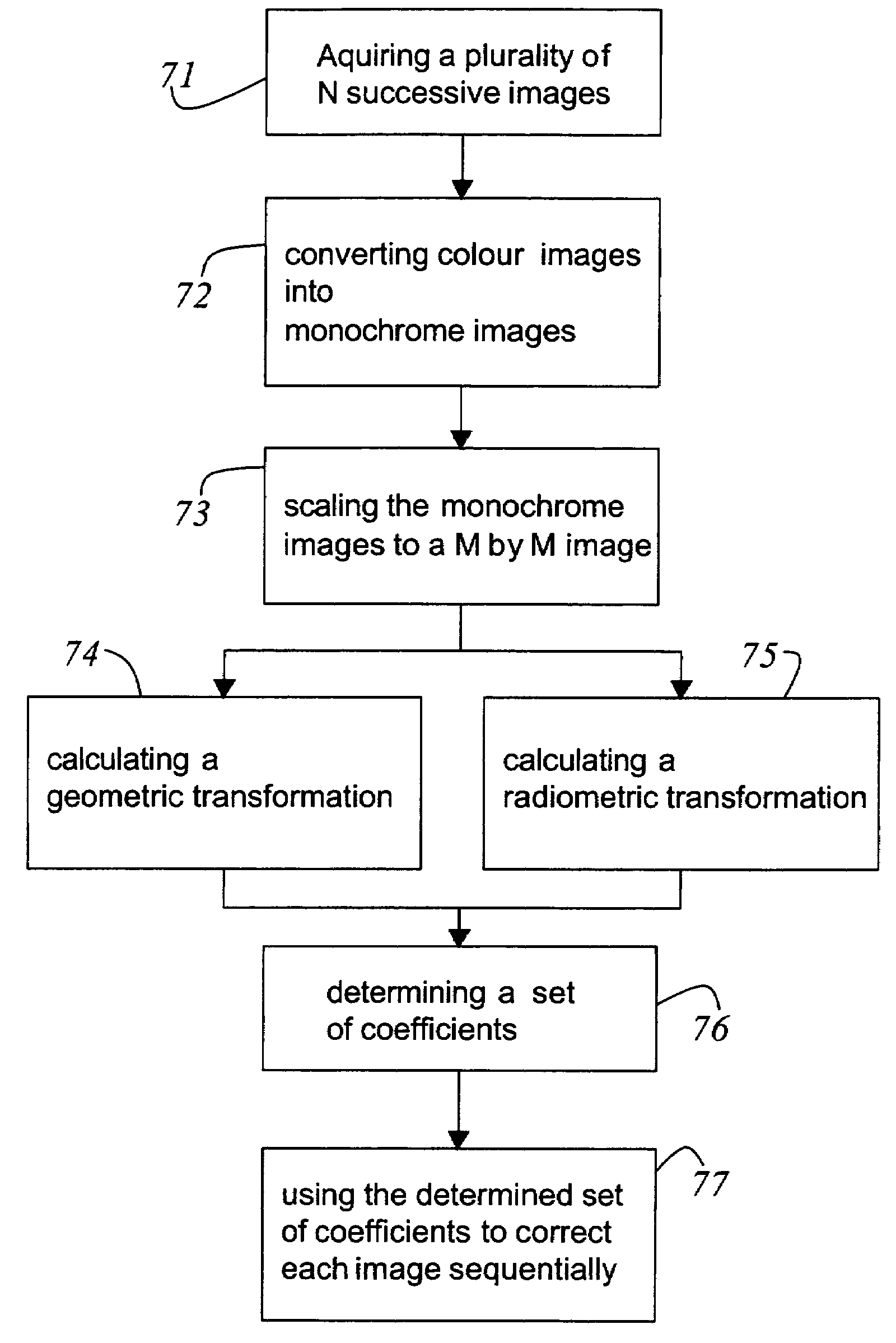
Method for correcting distortions in multi-focus image stacks
a multi-focus image and stack technology, applied in image data processing, microscopes, mountings, etc., can solve the problems of inability to talk multi-focus images, data can only be generated in very expensive fashion, and high level of technical complexity is also necessary
- Summary
- Abstract
- Description
- Claims
- Application Information
AI Technical Summary
Benefits of technology
Problems solved by technology
Method used
Image

Examples
Embodiment Construction
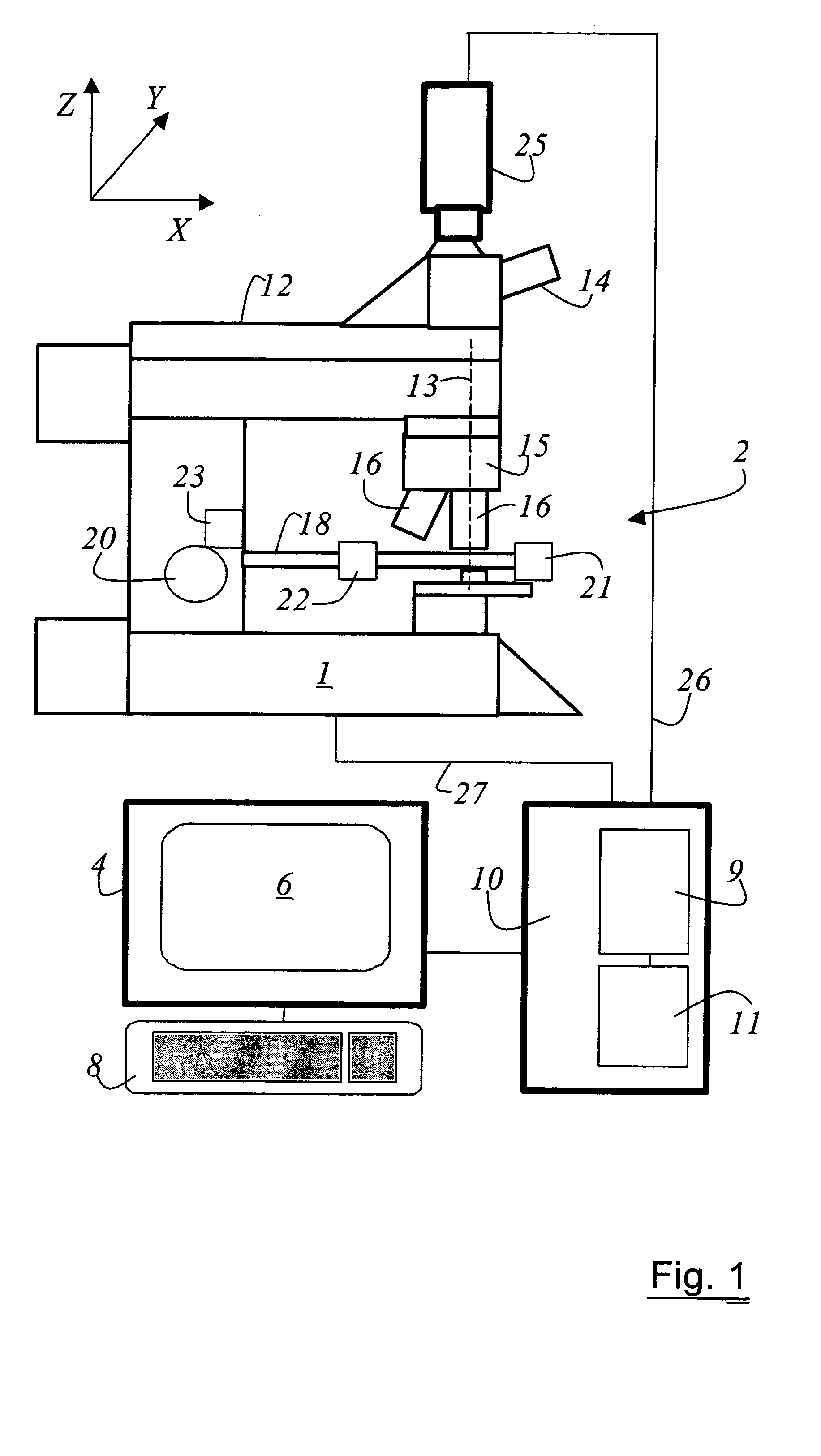
[0025]FIG. 1 is a schematic view of an optical system 2 for acquiring multifocus image stacks. The embodiment featured here shows a microscope 1, to which a computer 4 with a display 6 and an input device 8, as well as a control unit 10, for controlling and monitoring the various microscope functions are provided. The control unit encompasses a memory 9 and a microprocessor 11. The memory 9 and the microprocessor 11 are utilized by the method for correcting distortions in multi-focus image stacks. It is obvious to any person skilled in the art of correcting distortions in multi-focus image stacks, that the microscope can be a inverted microscope or a stereo microscope as well. The graphical description of the optical system 2 as shown in FIG. 1 should not limit the scope of the invention. The microscope 1 has a stand 12, to which at least one ocular 14, at least one objective 16 and a microscope stage 18 are attached. The embodiment shown in FIG. 1 has a microscope stage 18 can be d...
PUM
 Abstract
Description
Claims
Application Information