Evacuation route planning tool

a technology for evacuation routes and planning tools, applied in the field of ground transportation management, can solve the problems of large gis databases, inability to provide information to commercial and consumer markets, and delay in responding to calls, so as to maximize traffic flow and minimize the transit time of the flow

Inactive Publication Date: 2008-03-25
THE BOEING CO
View PDF8 Cites 295 Cited by
  • Summary
  • Abstract
  • Description
  • Claims
  • Application Information

AI Technical Summary

Benefits of technology

[0018]A method in accordance with the present invention comprises determining routes for an emergency situation using a geographical information systems (GIS) database that represents a geographical area. In one embodiment of the present invention, the GIS database contains at least four data layers: roads, evacuation areas, population density, and safe destinations. The road layer describes the road network. It comprises a collection of road segments and their connectivity. The road segments are attributed with length, current and future speeds. These attributes allow for calculation of segment transit times. Attributes at the intersections allow for calculation of transit delays due to traffic lights and turning. The evacuation areas data layer describes the points and areas to be evacuated. The intersection of this data layer with the population density data layer determines the evacuation demand. The evacuation demand is the spatial distribution of people to be evacuated. The evacuation demand is intersected with the road network to create a source of evacuation flow. The safe destination data layer consist of points and areas that accept evacuation flow. A point destination could be an emergency shelter, hospital, or decontamination center. A destination area can represent the edge of the area to be evacuated. The safe destination data layer is intersected with the road data layer to determine what points of the road network can absorb flow. Evacuation routes are determined by maximizing the traffic flow between the evacuation area and the safe area, and minimizing the flow's transit time.

Problems solved by technology

For example, paramedics may be unaware that a given street is closed for repairs, and be delayed in responding to a call because the paramedics en route to an accident scene tried to use the street that is closed.
These systems also do not retain data for analysis after events have occurred to root out systemic problems or determine corrective actions.
The large GIS databases, even if combined with other services and data, do not have the capability to provide information to commercial and consumer markets for use in managing fleet and personal travel itineraries.
Even if the GIS databases were combined with existing services, the number of sensors and other data sources used to augment the GIS databases do not provide proper coverage to accurately predict or determine the optimal route between two points.
Even in large metropolitan areas, the percentage of roads monitored by sensors is a small fraction of the number of roads that are in service, and, as such, the data available cannot provide an accurate model of real-time traffic conditions.
Emergency operations centers typically do not have access to the tools necessary to dynamically identify the optimal routes for evacuation.
More complex incidents, such as wildfires and terrorist attacks, are more dynamic in nature, and the optimal evacuation plan cannot be predicted due to uncertainties in how the emergency will unfold prior to the actual event.

Method used


Image

  • Evacuation route planning tool
  • Evacuation route planning tool
  • Evacuation route planning tool

Examples


Embodiment Construction

[0029]In the following description, reference is made to the accompanying drawings which form a part hereof, and which is shown, by way of illustration, several embodiments of the present invention. It is to be understood that other embodiments may be utilized and structural changes may be made without departing from the scope of the present invention.

Overview

[0030]Most state and local agencies use GIS to manage, plan, and record geographical information in their respective jurisdictions. However, these agencies use GIS solely as a mapping tool, rather than using the data in a dynamic manner for routing of vehicles.

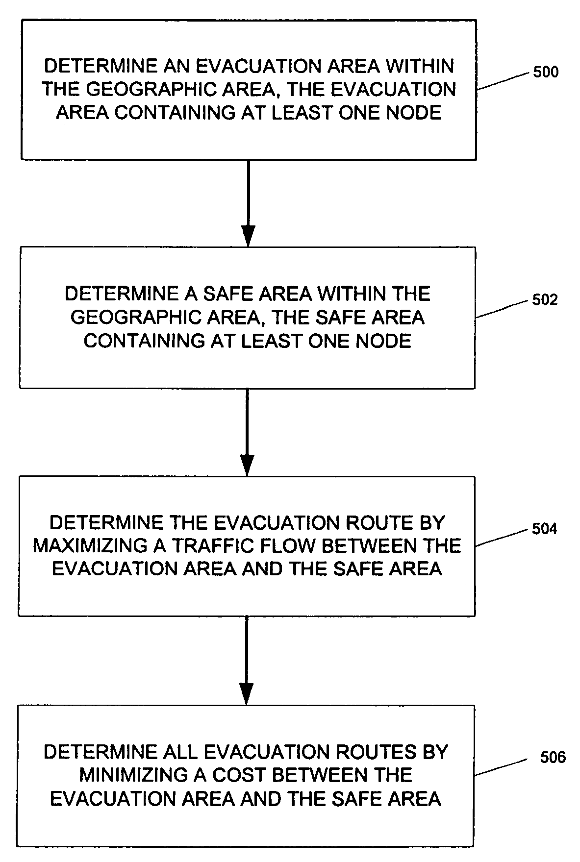
[0031]Emergency vehicles, commuters, and business fleet management services all can use GIS databases in a dynamic fashion to optimize routes for certain vehicles or for certain situations. For example, and not by way of limitation, if an emergency situation arises, such as the breakout of a large-scale fire, the GIS database can be used to determine the best evacuation r...


PUM


Abstract

A GIS-based system that determines evacuation routes for specific areas requiring evacuation. Evacuation and safe areas are determined, and evacuation routes plotted, based on emergency-specific information as well as road flow and estimated time of travel for each section of road between the evacuation area and safe area. Routes, evacuation areas, and safe areas are dynamically calculated and recalculated based on additional data, either real-time, historical, or other data added to the system, to compute optimal initial routes and redirect evacuees if changes in the emergency situation occur.

Description

CROSS-REFERENCE TO RELATED APPLICATIONS[0001]This application is related to the following co-pending and commonly-assigned patent applications, which applications are incorporated by reference herein:[0002]U.S. patent application Ser. No. 11 / 113,659, filed on the same date herewith, by Pauline Joe, Kenneth A. Cobleigh, and William F. Lyons, entitled “DYNAMIC ROUTING TOOL”;[0003]U.S. patent application Ser. No. 11 / 113,941, filed on the same date herewith, by Daniel J. Gadler, entitled “AGTM AIRBORNE SURVEILLANCE”;[0004]U.S. patent application Ser. No. 11 / 113,640, filed on the same date herewith, by Steven F. Cuspard, Daniel J. Gadler, Kenneth A Cobleigh, and Pauline Joe, entitled “ADVANCED GROUND TRANSPORTATION MANAGEMENT”;[0005]U.S. patent application Ser. No. 11 / 113,660, filed on the same date herewith, by Kenneth A. Cobleigh, Pauline Joe, Daniel J. Gadler, and Steven F. Cuspard, entitled “GEO-INFOSPHERE AS APPLIED TO DYNAMIC ROUTING SYSTEM”; and[0006]U.S. patent application Ser. N...

Claims


Application Information

Patent Timeline
Patent Type & Authority Patents(United States)
IPC IPC(8): G06F7/00
CPCG01C21/005G06Q10/047G08G1/096811G08G1/096844
Inventor BRUCE, ALAN E.COBLEIGH, KENNETH A.JOE, PAULINE
Owner THE BOEING CO
Why Eureka
Try Eureka