System and method for configuring a traffic control sensor system

a technology of traffic control and sensor system, applied in the field of system and method for configuring a traffic control sensor system, can solve the problems of failure to maintain the tracking of a vehicle during its travel through the entire user defined zone, forced stop of vehicles, and periodic stranding of vehicles at intersections

Active Publication Date: 2014-09-23
MS SEDCO
View PDF1 Cites 9 Cited by
  • Summary
  • Abstract
  • Description
  • Claims
  • Application Information

AI Technical Summary

Benefits of technology

[0016]The present invention is a microwave radar based traffic control system and method that makes intelligent decisions whether or not a vehicle is stranded (occluded) within a user defined zone adjacent to an intersection. A user defined zone is defined as a four-sided geographic area of the roadway which will be monitored by the traffic control system.
[0019]Modern computerized traffic control systems operate in either an open or closed mode. While operating in closed mode a traffic control system considers no input from external sensors and instead relies solely upon preprogrammed algorithms for providing timed light cycles for each traffic lane or sets of traffic lanes that approach a monitored intersection. While operating in closed mode the traffic control system may be preprogrammed to lengthen or shorten green light times for given traffic lanes during different times of the day or during different days of the week. For example, where a main artery of traffic intersects with a residential street carrying less traffic, it is quite common to preprogram the traffic control system to provide a longer green light time for the heavier traffic flow traveling along the main artery in comparison to infrequent traffic present at the intersecting residential street. In a more specific example, it may be desirable to provide a longer green light to a particular set of traffic lanes which are adjacent to a business or school when its occupants thereof are released at predictable times. In this instance it is presumed by the traffic control operator that a certain portion of said released occupants will be entering the adjacent traffic lanes at such predetermined release times, and therefore longer green lights for the adjacent lanes will be desirable during those times of heavy traffic volume.
[0020]Flexibility in programming the duration of green light time is intended to make the intersection operate in an efficient manner by maximizing traffic flow where known re-occurring factors that affect traffic volume are present. In any event, a traffic control system operating in closed mode loops through a preprogrammed timed red, yellow, and green light cycle algorithm irrespective of the actual volume of traffic that is present upon the roadway. As such, the efficiency of traffic control systems operating in closed mode is reduced whenever traffic volumes and flows are unpredictable, which is most of the time.
[0029]It is well known in the prior art of external sensors that user defined zones can be established in areas monitored by an external sensor. User defined zones are usually defined as a left turn lane (where present), a right turn lane (where present), and through lanes. By defining certain parts of approaching traffic lanes as zones, the sensor can precisely monitor exact portions of the approaching traffic lanes.

Problems solved by technology

Being stranded means that a vehicle is forced to stop and wait at a red traffic light even though the traffic control system would have otherwise eventually provided a green light if it were aware of the vehicle's presence at the intersection.
Vehicles periodically become stranded at an intersection because they are occluded.
In other words, failing to maintain tracking of a vehicle during its travel through the entire user defined zone is called occlusion.

Method used


Image

  • System and method for configuring a traffic control sensor system
  • System and method for configuring a traffic control sensor system
  • System and method for configuring a traffic control sensor system

Examples


Embodiment Construction

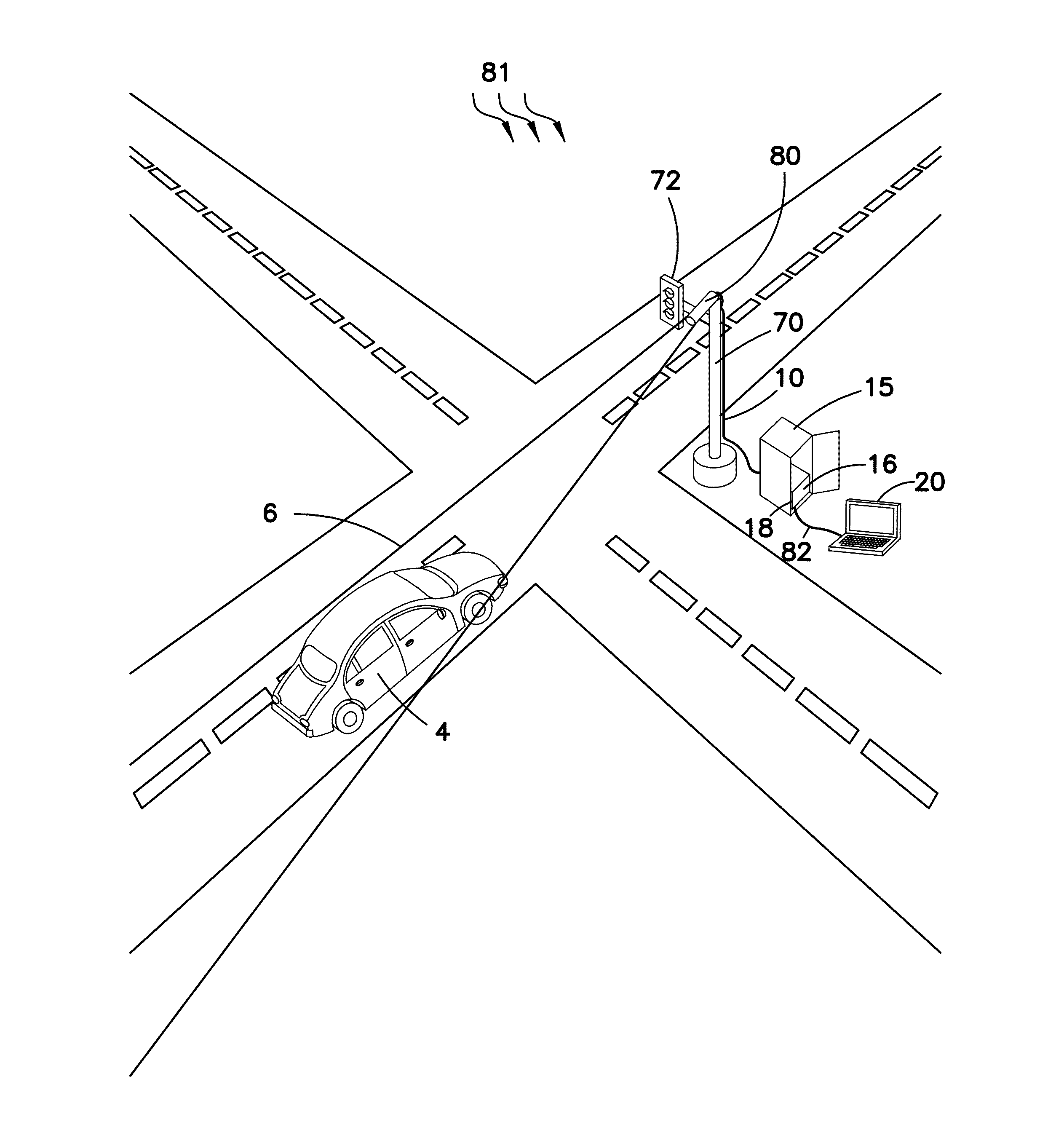
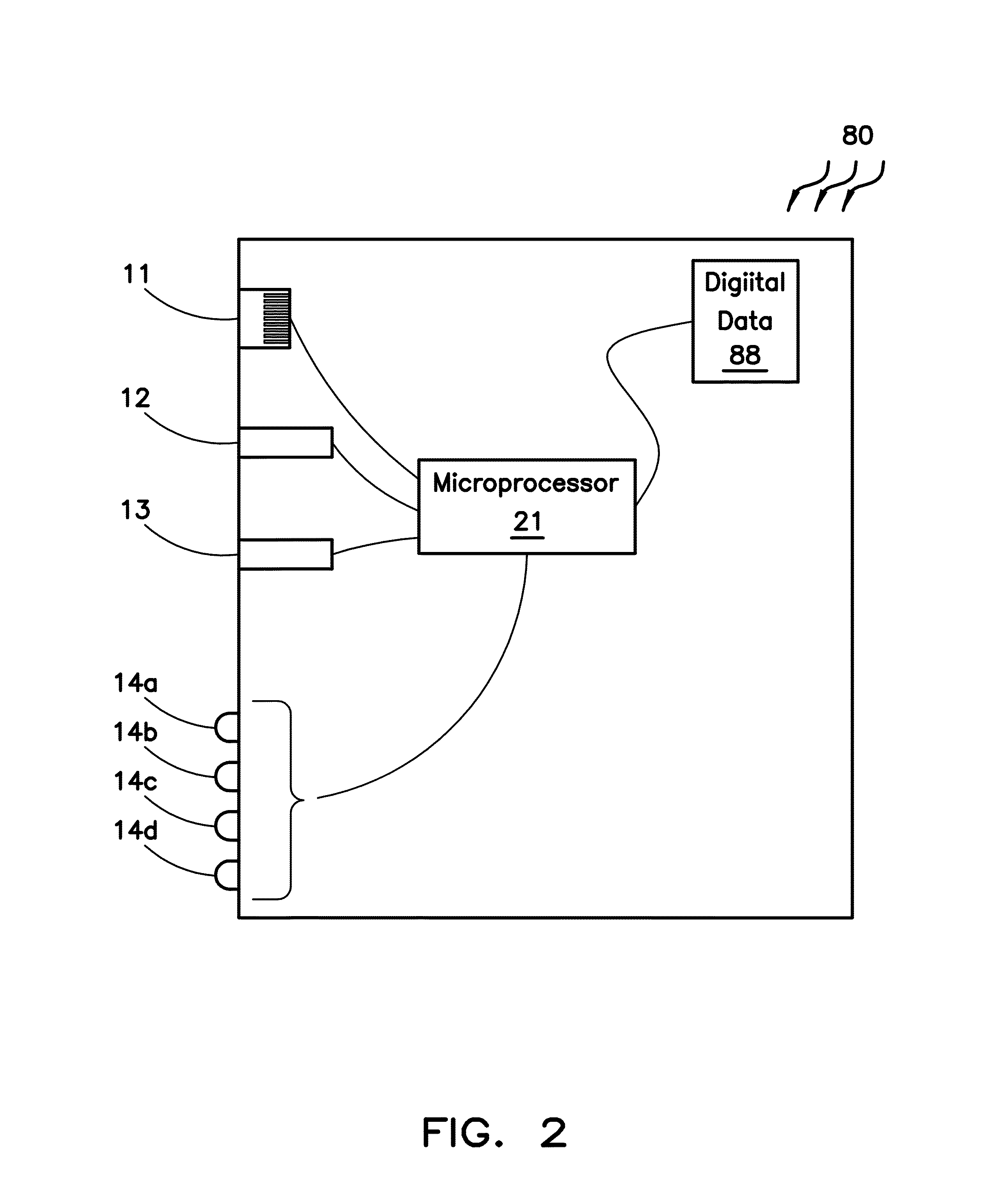
[0047]The present invention is a system and method for a traffic control sensor system that becomes integral with a separate traffic control system operating in open mode. The present traffic control sensor system is further defined as one or more standalone microwave radar transceivers (“sensors”) and a cooperative electronic data bus card (“Traffic Control Interface Card” or “TCIB”). The sensor is in electrical communication with the TCIB via an Ethernet cable, and electrical connectors of the TCIB are in electrical connection with the traffic control system via its electrical communicative slot resident upon the motherboard of the traffic control system.

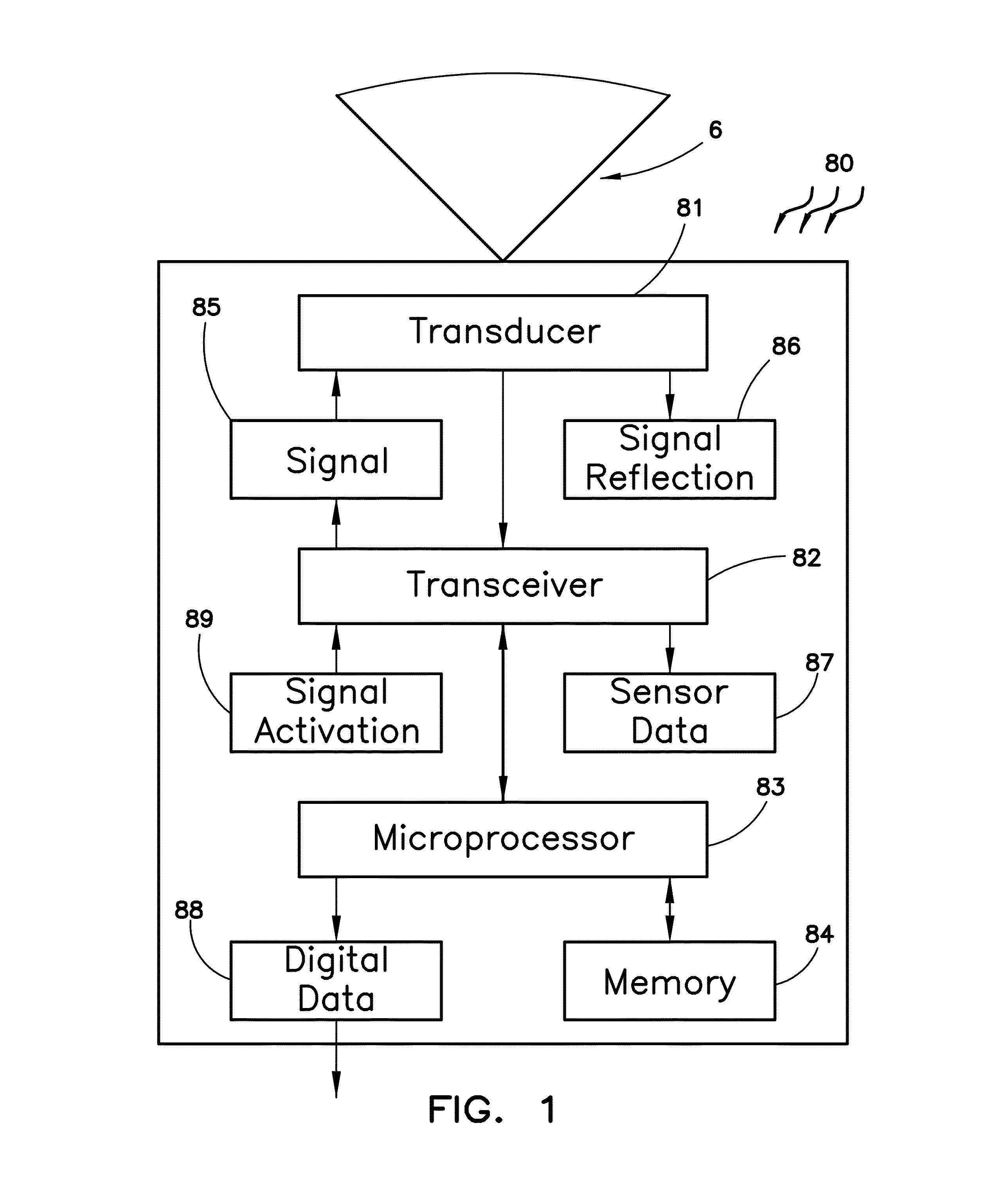
[0048]The traffic control sensor system of the present invention utilizes one or more microwave sensors (sensors) to detect non-stationary vehicles moving across the monitored piece of roadway or surface which carries vehicles. For purposes of the present invention, a pedestrian on foot, skateboard, bicyclist, or other mobile vess...


PUM


Abstract

A traffic control sensor system which provides outputted signals to a receiving traffic control system to assist the traffic control system in making real-time informed green light decisions. Such signals received by the traffic control system include calls for a green light for monitored traffic lanes approaching an intersection. The traffic control sensor system employs various techniques to reduce the number of vehicles that are dropped or occluded. A vehicle is considered to be dropped or occluded whenever the traffic control sensor system first detects the vehicle entering a user defined zone within the approaching lanes to the intersection, and then fails to detect or monitor such vehicle exiting the user defined zones. Occlusion or dropping may occur whenever a sensor is malfunctioning, certain environmental conditions are present, or during any time the sensor's detection signal is interrupted such as from cross traffic entering the monitored intersection.

Description

RELATED APPLICATIONS[0001]Not Applicable.FIELD OF THE INVENTION[0002]The present invention relates is directed to traffic control indicators for detecting and controlling vehicle traffic at or about a roadway intersection. More particularly the present invention uses one or more radar transceivers and a detection system in combination with traffic control devices to facilitate an orderly and effective flow of vehicle traffic though said intersection. The term vehicle as used herein shall include any vessel which is utilized for travel or which exhibits movement. For purposes of the present invention, a pedestrian on foot, skateboard, bicyclist, or other mobile vessel is also considered a vehicle. A traffic control device as used herein is defined as any device which emits or causes the emission of any light, sound and / or movement to indicate a traffic condition.BACKGROUND OF THE INVENTION[0003]The use of traffic control devices to provide a means for a safe and orderly flow of vehic...

Claims


Application Information

Patent Timeline
Patent Type & Authority Patents(United States)
IPC IPC(8): G08B21/00
CPCG01S13/91G08G1/08
Inventor WIGNOT, LEROY SAMUELWANG, WEI
Owner MS SEDCO
Why Eureka
Try Eureka