Method for improving optical proximity correction

a technology of optical proximity and correction method, which is applied in the field of semiconductor integrated circuit (ic) process technology, can solve the problems of loss of mask shape fidelity, the limit of the lithographic process capacity, and the difficulty in designing tools for automating chip design, so as to improve the variation of line width across the chip

Active Publication Date: 2008-03-25
GLOBALFOUNDRIES U S INC
View PDF24 Cites 245 Cited by
  • Summary
  • Abstract
  • Description
  • Claims
  • Application Information

AI Technical Summary

Benefits of technology

[0015]It is therefore an objective of the present invention to provide a method and system for designing masks, for example, by performing model-based optical proximity correction (MBOPC), that improves across-chip line-width variations.
[0017]It is yet a further objective of the present invention to provide an MBOPC method and system that is robust and will converge to a final mask design that minimizes defects.

Problems solved by technology

The advent of advanced lithographic techniques and the attempt of chip manufacturers to closely follow Moore's law predicting an exponential growth of number of components on a chip and their shrinkage on the wafer is making the process of designing tools for automating the chip design extremely challenging.
As the components on the chip become smaller, they are now in the verge of reaching the limits of capacity of the lithographic process.
One of the most common problem of printing integrated circuits on silicon wafers from the mask using lithographic processing is the loss of fidelity of the mask shapes.
The non-linearities associated with this lithographic process of imprinting and the laws of physics associated with light (including diffraction of light waves) makes impressing highly unpredictable.
RET processes may require heavy overexposure and large etch trim, which can pose a significant challenge to the OPC algorithm, since large discrepancies exist between mask size and actual on-wafer target size.
Since the OPC algorithm corrects the mask shapes based on simulated target shapes, the fixed corrections applied to the mask shapes may result in over-correction or under-correction which may converge to a solution only with difficulty, or may not converge at all.
In addition, even if a solution is found, there may be large across-chip line width variation (ACLV), and in particular, problems in controlling the gate and polysilicon line widths.
The simulation of the image at points on the mask is computationally very expensive, and is typically limited to selected points.
The main problem with this solution is that the large notch 705″ at segment F1 can cause a very narrow feature to be printed.
This separation D causes some simulation sites to be overrun by the mask edge, resulting in the simulation site not accurately predicting the behavior along the segment.

Method used


Image

  • Method for improving optical proximity correction
  • Method for improving optical proximity correction
  • Method for improving optical proximity correction

Examples


Embodiment Construction

[0037]In the following description, numerous specific details may be set forth to provide a thorough understanding of the present invention. However, it will be obvious to those skilled in the art that the present invention may be practiced without such specific details.

[0038]Refer now to the drawings wherein depicted elements are not necessarily shown to scale and wherein like or similar elements are designated by the same reference numeral through the several views.

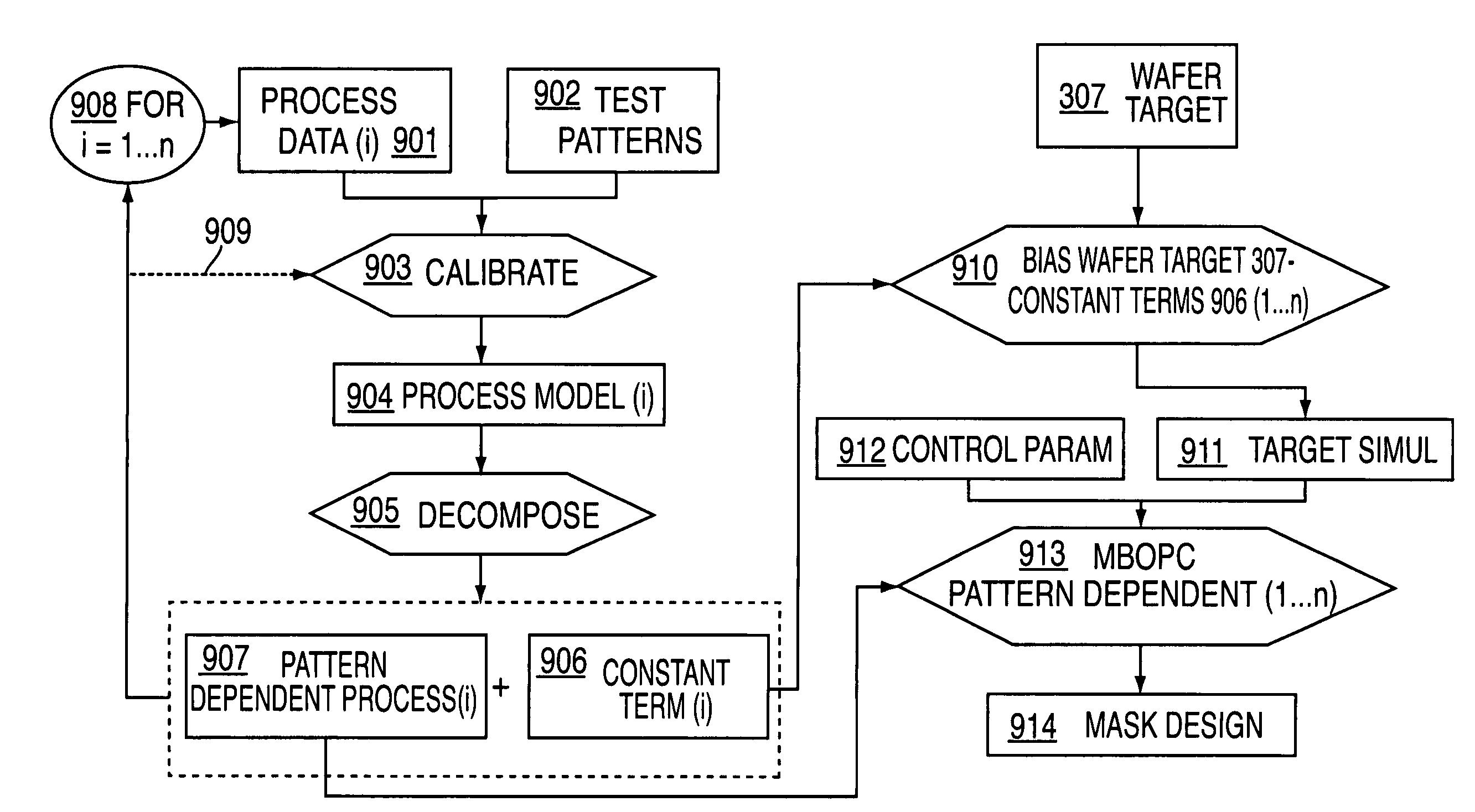
[0039]Referring to FIG. 3, a flow diagram of a conventional model based optical proximity correction (MBOPC) process is illustrated. The MBOPC process consists of two major sections: the creation of a model, referred to as Model Build 60, including Blocks 301-304, and the use of that model to create a photomask design based on the design of the semiconductor integrated circuit to be formed on a wafer, referred to as Data Prep 30, including Blocks 307-310. The model build process 60 is generally carried out one time for ...


PUM

PropertyMeasurementUnit
optical proximityaaaaaaaaaa
wavelengthaaaaaaaaaa
widthaaaaaaaaaa

Abstract

A method for performing model based optical proximity correction (MBOPC) and a system for performing MBOPC is described, wherein the process model is decomposed into a constant process model term and a pattern dependent portion. The desired wafer target is modified by the constant process model term to form a simulation target that is used as the new target within the MBOPC process. The pattern dependent portion of the model is used as the process model in the MBOPC algorithm. This results final mask designs that result in improved across-chip line width variations, and a more robust MBOPC process.

Description

BACKGROUND OF INVENTION[0001]The present invention relates in general to semiconductor integrated circuit (IC) process technology, particularly, photolithography used in fabrication of semiconductor ICs, and more particularly to optical proximity correction.[0002]The advent of advanced lithographic techniques and the attempt of chip manufacturers to closely follow Moore's law predicting an exponential growth of number of components on a chip and their shrinkage on the wafer is making the process of designing tools for automating the chip design extremely challenging. The chip is imprinted by means of optical lithographic techniques on the silicon wafer by way of chrome on glassmasks. As the components on the chip become smaller, they are now in the verge of reaching the limits of capacity of the lithographic process.[0003]One of the most common problem of printing integrated circuits on silicon wafers from the mask using lithographic processing is the loss of fidelity of the mask sh...

Claims


Application Information

Patent Timeline
Patent Type & Authority Patents(United States)
IPC IPC(8): G06F17/50G03F1/00
CPCG03F1/144G03F1/36G03F7/70433G03F7/70441
Inventor CUI, YUPINGMANSFIELD, SCOTT M.
Owner GLOBALFOUNDRIES U S INC
Why Eureka
Try Eureka