Tooling assembly

Inactive Publication Date: 2008-04-01
LISK RODGER A +1
View PDF9 Cites 3 Cited by
  • Summary
  • Abstract
  • Description
  • Claims
  • Application Information

AI Technical Summary

Benefits of technology

[0011]It is a first non-limiting object of the present invention to provide a tooling assembly wh

Problems solved by technology

While current roll tooling assemblies do allow for the formation of cuts and / or slits within a sheet of material, they suffer from some drawbacks.
Such blades become dull within a relatively short period of time, thereby requiring frequent maintenance and / or replacement and undesirably and frequently disrupting the overall forming process.
Hence, costs are incurred in maintaining the tooling assembly and in the frequent “maintenance downtime” associated with this type of tooling assembly.
Moreover, these steel blades tend to “flex” or move over time, thereby increasing the likelihood of the entry of dust and / or other ambient type particulates (e.g., such as that which is created during the roll forming process) between the blades.
The entry of such foreign matter causes the blades to expand and / or move in separation (i.e., dust or other particulates resultant from the forming process becomes “built-up” over time, thereby forcing the blades to move away from or separate from the other blades) and impairs their operative mating arrangement, thereby further causing increased wear and the creation of items which have undesirably positioned slits or openings.
While a carbide blade has many superior benefits to a steel blade, it also has many serious drawbacks.
By way of example and without limitation, a carbide blade easily shatters or becomes damaged due to its brittleness.
Hence, vibration or other forces, such as and without limitation, material “jam-ups” (e.g., a material “jam-up” hereinafter refers to the material which the blades are forming being caught around or wedged around the blades, thereby forcing the blades to form two layers of material rather than one layer of material), acting upon the blade in a manufacturing environment, oftentimes cause the blade to be destroyed or damaged.
Further, the relatively high cost of a carbide blade has made this alternative unpalatable.

Method used


Image

  • Tooling assembly
  • Tooling assembly
  • Tooling assembly

Examples


Embodiment Construction

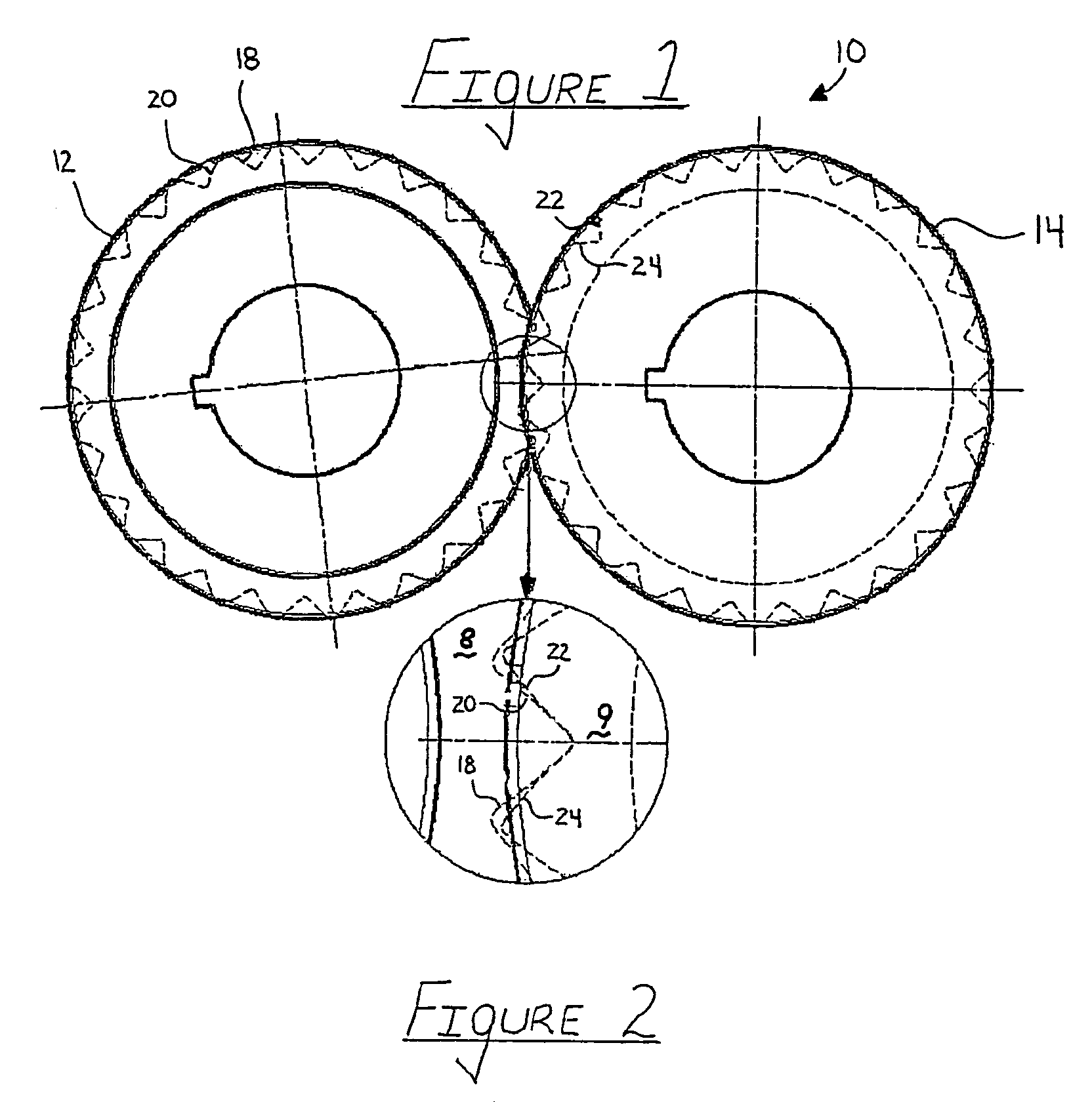
[0023]Referring now to FIGS. 1 and 2, there is shown a side view of a roll forming tool assembly 10 which is made in accordance with the teachings of the preferred embodiment of the invention.

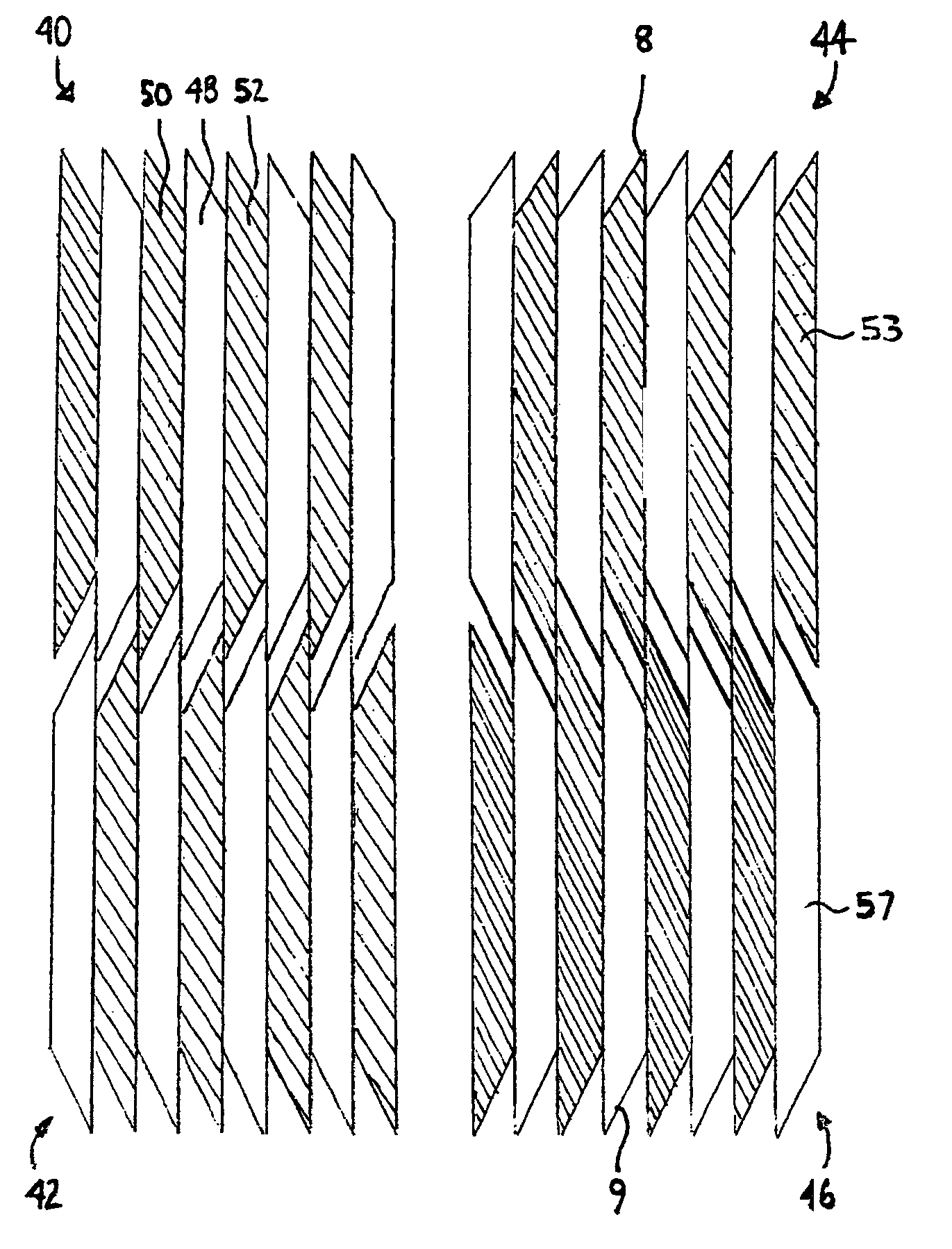
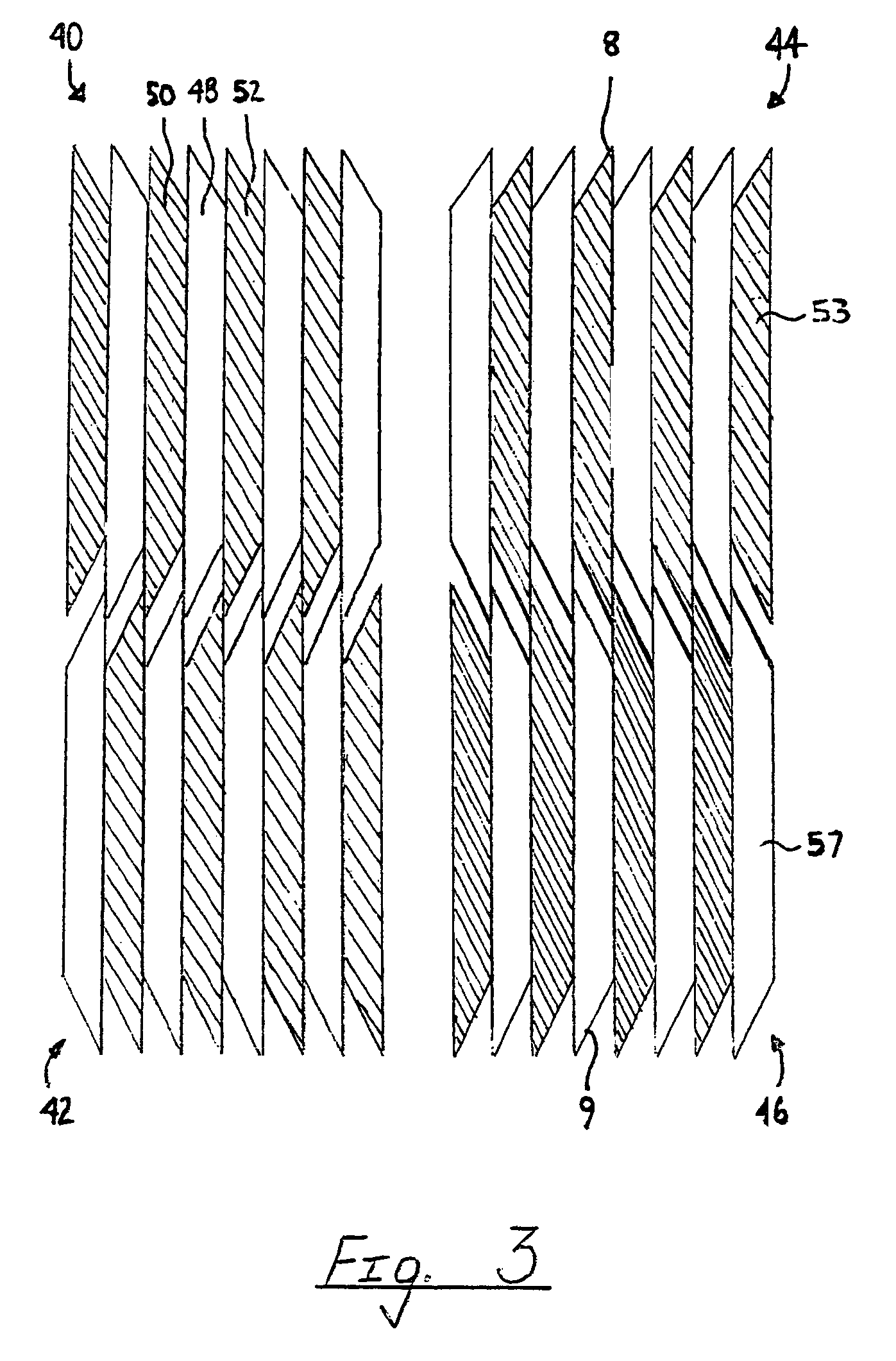
[0024]Particularly, the roll forming tool assembly 10 includes a first selectively rotatable member 12 and a second selectively rotatable member 14. As shown, selectively rotatable member 12 includes several blades, each blade includes multiple louver cutting edges, such as louver edges 18, 20, while selectively rotatable member 14 includes several cutting edges, such as edges 22, 24. In the most preferred embodiment of the invention, the blade 9 is made from a first material, such as steel, while blade 8 is made from a second material, such as carbide. Hence, each blade, such as blade 8, which is made from the second material and which is disposed upon the selectively rotatable member 12 is operatively positioned between two blades which are formed from the first material. Further, as shown, e...


PUM

PropertyMeasurementUnit
Sizeaaaaaaaaaa
Shapeaaaaaaaaaa

Abstract

A tooling assembly 10 having a first set of blades which are formed from a first material and a second set of blades which are formed from a second material. More particularly, each carbide blade of each member 62, 64, 66, and 68 is operatively disposed between two steel blades.

Description

CROSS REFERENCE TO RELATED APPLICATIONS[0001]Not ApplicableSTATEMENT REGARDING FEDERALLY SPONSORED RESEARCH OR DEVELOPMENT[0002]Not ApplicableTHE NAMES OF THE PARTIES TO A JOINT RESEARCH AGREEMENT[0003]Not ApplicableINCORPORATION BY REFERENCE OF MATERIALS SUBMITTED ON A COMPACT DISK[0004]Not ApplicableFIELD OF INVENTION[0005]The present invention generally relates to a tooling assembly and more particularly, to a form roll tooling assembly which is used to selectively cut and / or slit sheet type material in a desired manner.BACKGROUND OF THE INVENTION[0006]A form roll tooling assembly selectively cuts and / or slits a sheet of material in order to allow the material to be used in the manufacture of a heat exchanger, such as but not limited to a radiator, heat core, evaporator, and / or condenser. Particularly, the formed cuts or slits promote and direct the flow of air through the formed exchanger. While current roll tooling assemblies do allow for the formation of cuts and / or slits with...

Claims


Application Information

Patent Timeline
IPC IPC(8): B21D13/00B02C1/08B26D7/06B02C1/10
CPCB21D31/046B23D19/08B26D1/245B26D1/0006B26D2001/0046B26D2001/006Y10T83/0481Y10T83/6588
Inventor LISK, RODGER A.PERAZA, MANNY WILLIAM
Owner LISK RODGER A
Why Eureka
Try Eureka