
Air filtration system control

a technology of air filtration system and control panel, which is applied in the direction of electric supply technique, dispersed particle separation, separation process, etc., can solve the problems of filter efficiency drop and the general requirement of frequent maintenance of the filter typ

Active Publication Date: 2008-04-01
TRANE INT INC
View PDF34 Cites 74 Cited by
  • Summary
  • Abstract
  • Description
  • Claims
  • Application Information

AI Technical Summary

Benefits of technology

The control system enhances the efficiency and longevity of air filtration by regulating power supply, monitoring conditions, and providing user-friendly maintenance alerts, thus maintaining high filtration efficiency and reducing maintenance frequency while being cost-effective for HVAC systems.

Problems solved by technology

As dirt accumulates on the filter plates, the efficiency of the filter drops and thus this type of filter generally requires frequent maintenance.
The implementation of intense field dielectric filters has, however, posed certain problems in the development of a practical, cost effective filter system that may be incorporated in HVAC equipment, attached as an add-on to HVAC equipment and utilized as a stand-alone filter interposed in an air flow duct, for example.

Method used


Image

  • Air filtration system control
  • Air filtration system control
  • Air filtration system control

Examples


Embodiment Construction

[0035]In the description which follows, like parts are marked throughout the specification and drawing with the same reference numerals, respectively. The drawing figures are not necessarily to scale and certain features may be shown in schematic or somewhat generalized form in the interest of clarity and conciseness.

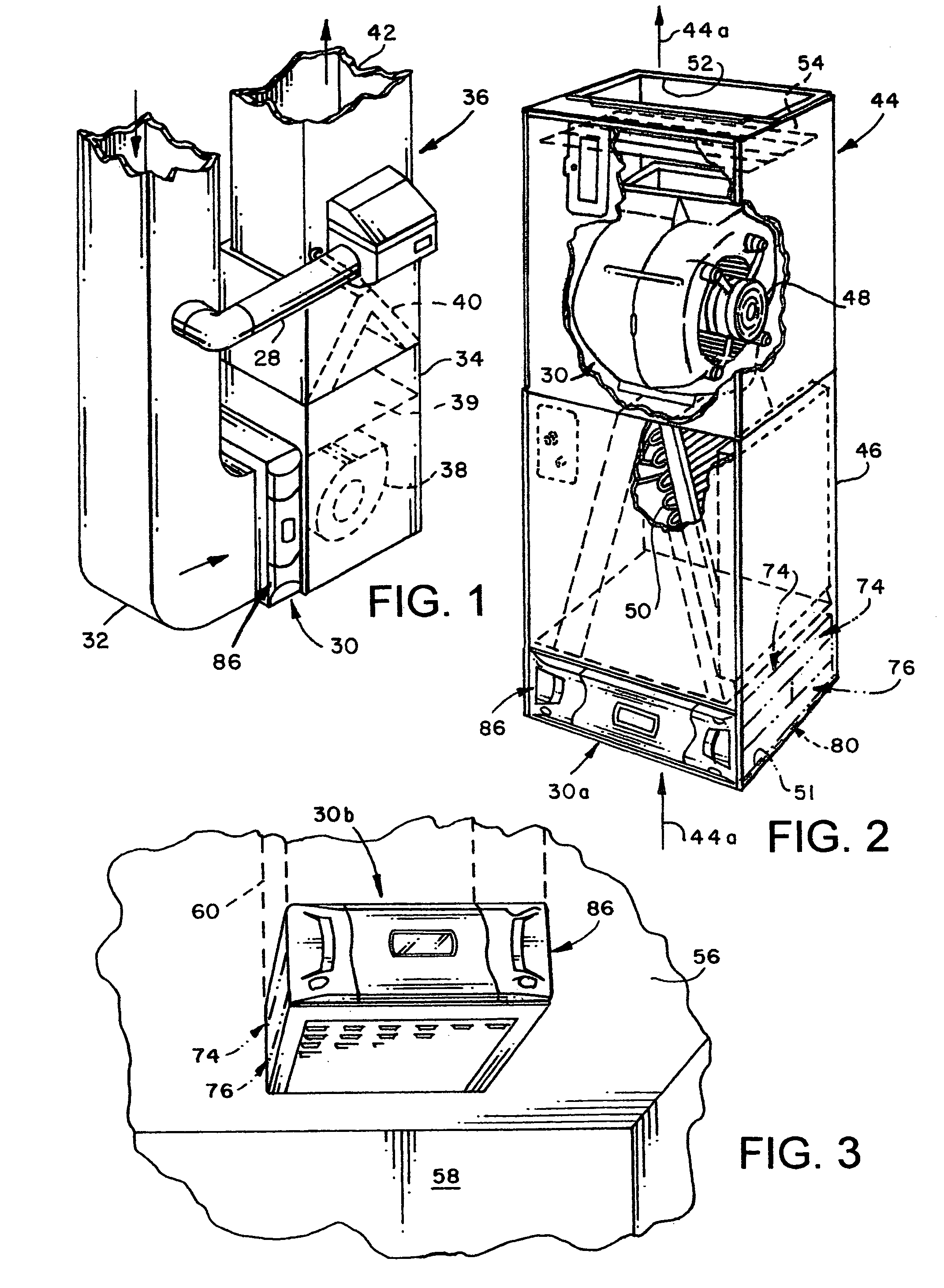
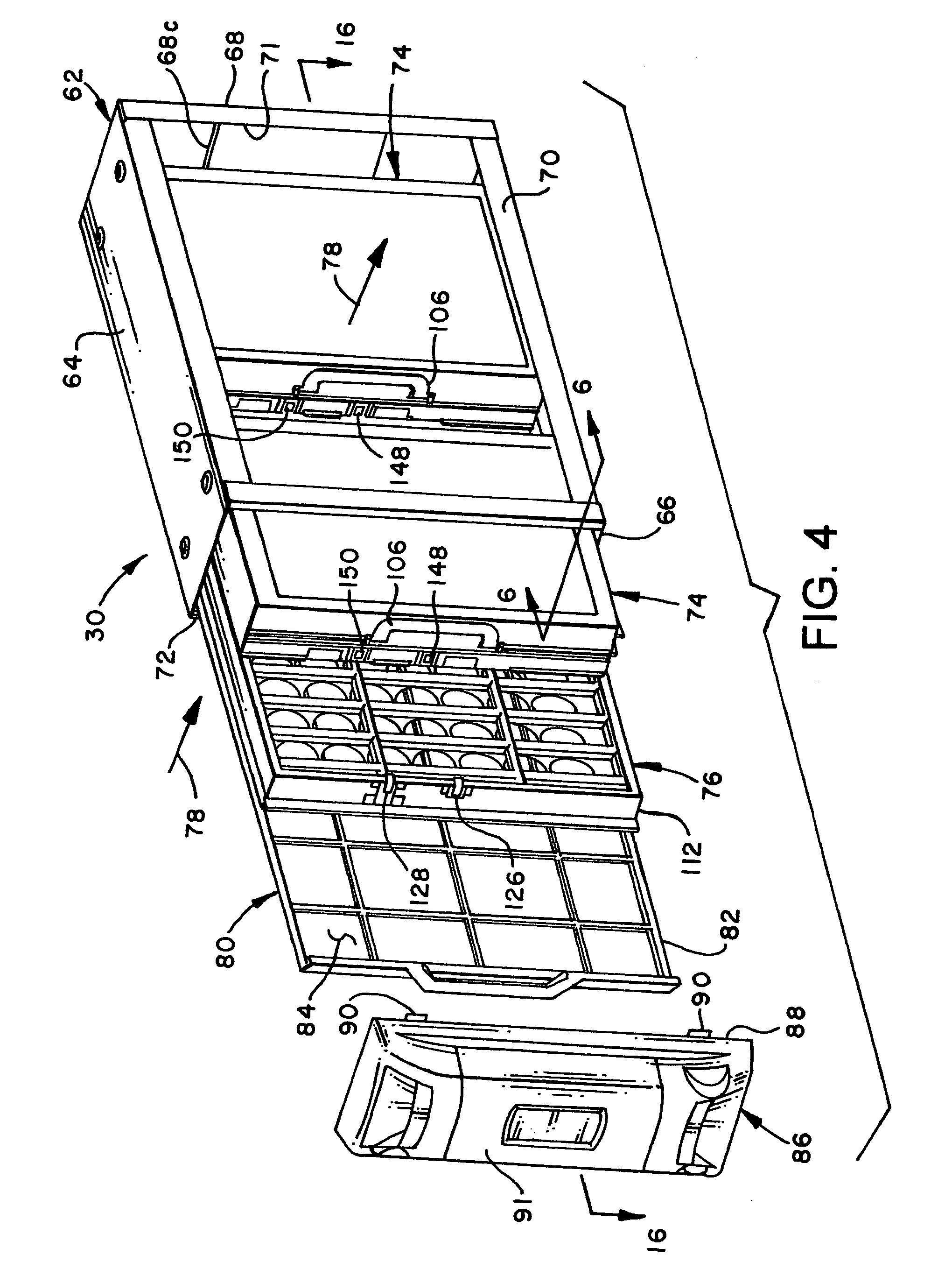
[0036]Referring now to FIG. 1, there is illustrated an embodiment of the invention comprising an intense field dielectric air filtration system, generally designated by the numeral 30. The filtration system 30 is shown interposed in an air flowpath from a return air duct 32 leading to the interior of a cabinet 34 for an air conditioning unit 36. The air conditioning unit 36 includes conventional components such as a motor driven fan 38, a furnace heat exchanger 39 and a heat exchanger 40 which may be part of a vapor compression air conditioning system and which may or may not be reversible so that the air conditioning unit 36 may be capable of providing one, or the othe...


PUM

PropertyMeasurementUnit
voltageaaaaaaaaaa
voltageaaaaaaaaaa
voltageaaaaaaaaaa

Abstract

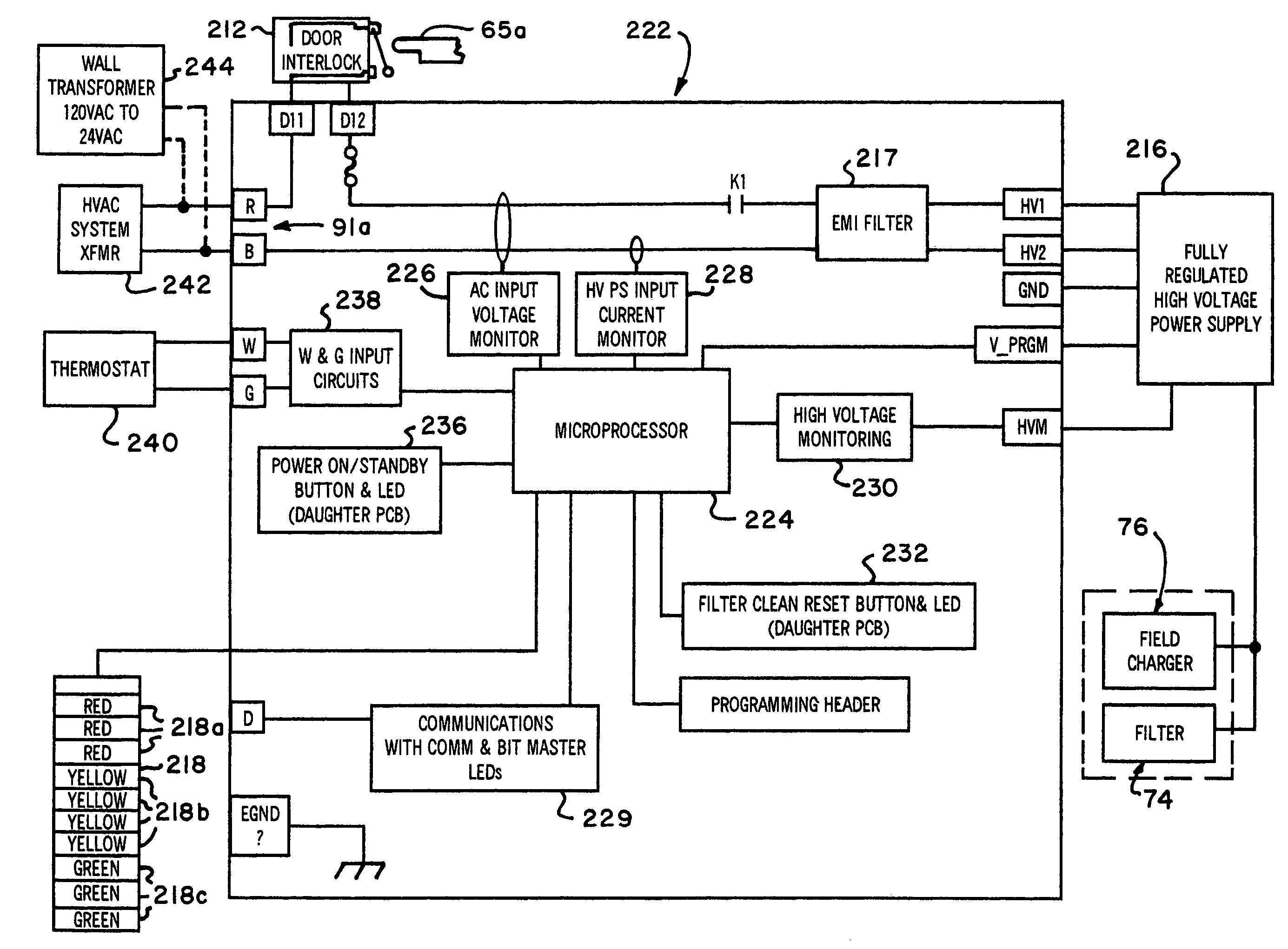
An intense field dielectric air filtration system associated with an air conditioning unit includes a microprocessor based control system which may be connected to the thermostat of the air conditioning unit to energize the air filtration system in response to a call for heat or cooling signal at the thermostat or startup of the fan motor for the air conditioning unit. The control system includes a power supply for the air filtration system together with voltage and current monitoring circuits for detecting a fault condition. Filtration system on / off and timing function reset switches are connected to the microprocessor and visual displays, including a multicolored LED bargraph display, are controlled by the microprocessor to indicate voltage potential applied to the air filtration system, a fault condition or a test mode.

Description

BACKGROUND OF THE INVENTION[0001]The filtration of air being circulated by and through heating, ventilating and air conditioning (HVAC) equipment has become an increasingly desirable and necessary process. Historically, air filtration systems and devices associated with HVAC equipment have been provided to maintain the equipment in a state of cleanliness and high efficiency. However, in recent years, the filtration of indoor air has become important to maintain and improve human health and to keep interior rooms and furnishings more clean.[0002]Air filter selection criteria includes filter dirt collection “efficiency”, air pressure drop across the filter, available space for the filter system, dirt or dust holding capacity of the system and, of course, initial and replacement costs. With regard to the filtration of indoor air in residential dwellings and commercial facilities, there has been an increasing need for filters which will perform suitable particle filtration. Conventional...

Claims


Application Information

Patent Timeline
Patent Type & Authority Patents(United States)
IPC IPC(8): B03C3/68
CPCB03C3/12B03C3/68B03C3/09B03C3/155B03C3/47B03C2201/10
Inventor HELT, ROBERT W.VENDT, STEPHEN J.BOYDSTUN, ROGER L.HAGAN, J. MARK
Owner TRANE INT INC
Learn More