
Transconductance circuit for piezoelectric transducer

a piezoelectric detector and transconductance circuit technology, applied in the field of piezoelectric detector systems, can solve the problems of relatively expensive high impedance operational amplifiers for piezoelectric detectors

Active Publication Date: 2008-04-01
SUREN SYST
View PDF9 Cites 18 Cited by
  • Summary
  • Abstract
  • Description
  • Claims
  • Application Information

AI Technical Summary

Problems solved by technology

As understood herein, heretofore transconductance circuits for piezoelectric detectors have required relatively expensive high impedance operational amplifiers as a result of having to measure small amounts of charge produced by piezoelectric detectors.

Method used


Image

  • Transconductance circuit for piezoelectric transducer
  • Transconductance circuit for piezoelectric transducer
  • Transconductance circuit for piezoelectric transducer

Examples


Embodiment Construction

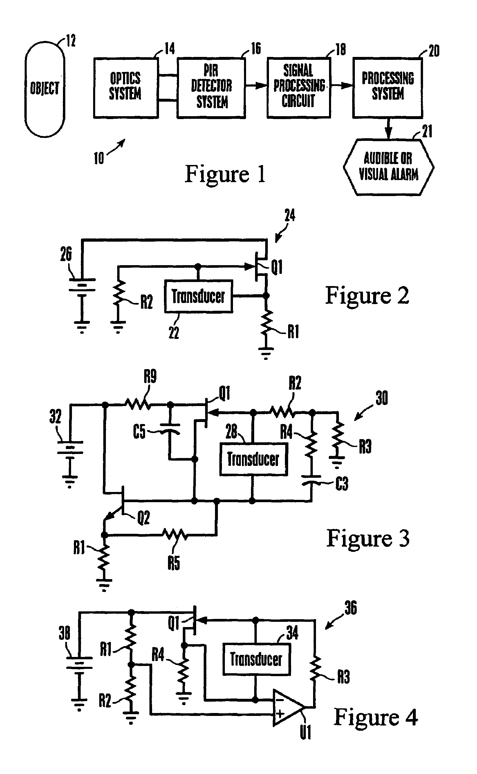
[0029]Referring initially to FIG. 1, an exemplary non-limiting system is shown, generally designated 10, for detecting a moving object 12, such as a human. The system 10 includes an optics system 14 that can include appropriate mirrors, lenses, and other components known in the art for focussing images of the object 12 onto a passive infrared (PIR) detector system 16. In response to the moving object 12, the PIR detector system 16 generates a signal that can be filtered, amplified, and digitized by a signal processing circuit 18, with a processing system 20 (such as, e.g., a computer or application specific integrated circuit) receiving the signal and determining whether to activate an audible or visual alarm 21 or other output device such as an activation system for a door, etc.

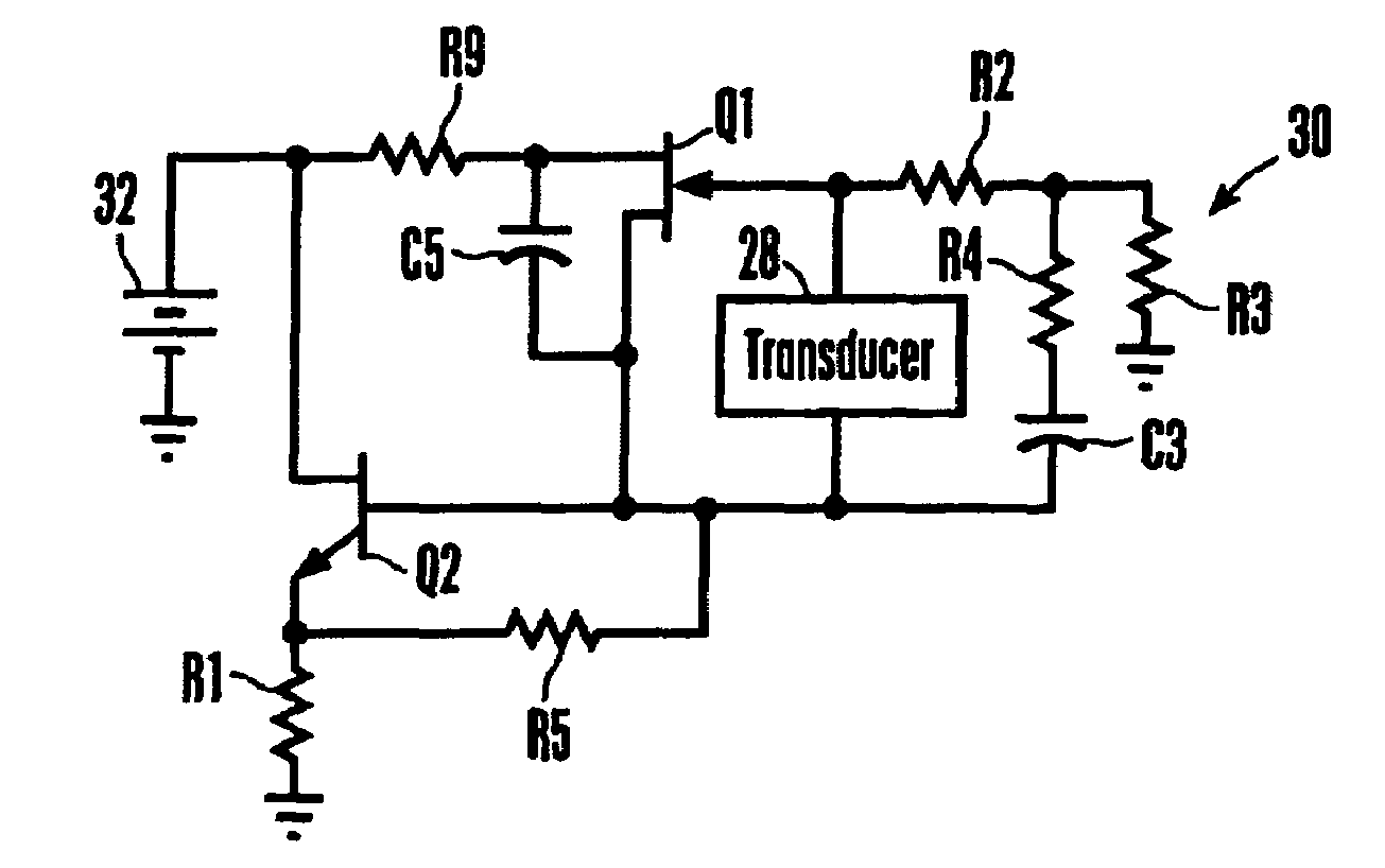
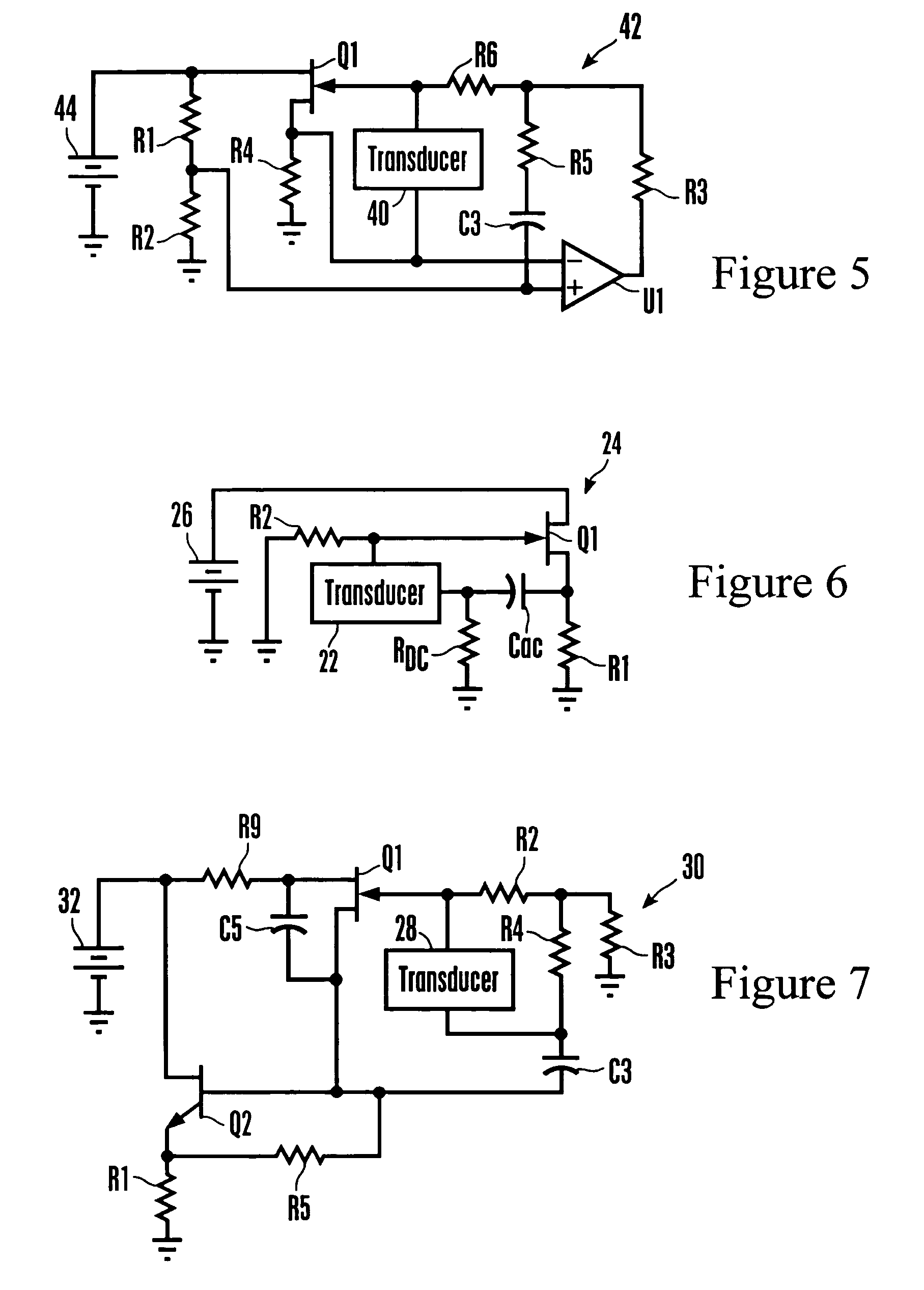
[0030]Having described one application of the piezoelectric detector of the present invention, attention is now directed to FIGS. 2-5, which show various implementations of the present inventive concept. As ...


PUM


Abstract

A transconductance monitoring and amplifying circuit for a piezoelectric transducer that may be used in, e.g., a motion detector system includes a FET, with the transducer (and, hence, the signal voltage reference) floating between the gate and source of the FET, as opposed to being connected to the common ground of the circuit. This permits the development of a larger detector signal and concomitantly the use of a relatively inexpensive FET instead of a relatively more expensive high impedance operational amplifier as must be used in conventional transconductance circuits. The FET and transducer can be held in a single four-pin package. A discrete time sampled operational amplifier may also be used.

Description

RELATED APPLICATIONS [0001]This is a continuation-in-part of and claims priority from U.S. patent application Ser. No. 10 / 918,080, filed Aug. 13, 2004, now U.S. Pat. No. 7,141,910 which is a CIP of Ser. No. 10 / 812,603, filed Mar. 30, 2004, now U.S. Pat. No. 7,042,134 claiming priority in turn from U.S. provisional application Ser. No. 60 / 459,516, filed Mar. 31, 2003, all of which are incorporated herein by reference.FIELD OF THE INVENTION [0002]The present invention relates generally to piezoelectric transducer systems.BACKGROUND OF THE INVENTION [0003]Piezoelectric sensor systems are used in a wide variety of applications. As but one non-limiting example, some security systems detect movement in a monitored space using passive infrared (PIR) motion sensors, which detect changes in far infrared radiation (8-14 micron wavelength) due to temperature differences between an object (e.g. a human) and its background environment. Upon detection, motion sensors generally transmit an indicat...

Claims


Application Information

Patent Timeline
Patent Type & Authority Patents(United States)
IPC IPC(8): H01L41/08
CPCH01L41/042H03F1/34H03F3/181H03F3/347H03F3/45475H03F3/70H03F2203/45528H10N30/802
Inventor MICKO, ERIC SCOTT
Owner SUREN SYST
Learn More