Portable electronic appliance with a battery having a wireless tag containing battery information

a wireless tag and electronic appliance technology, applied in the field of portable electronic appliances and batteries, can solve the problems of battery life differences, electrical appliances becoming inability to perform photography immediately, energy warning, etc., and achieve the effects of reducing power consumption, increasing battery operating time, and automatically controlling the power consumption of portable electronic appliances

Inactive Publication Date: 2008-04-01
FUJIFILM CORP
View PDF10 Cites 15 Cited by
  • Summary
  • Abstract
  • Description
  • Claims
  • Application Information

AI Technical Summary

Benefits of technology

[0014]Another object of the present invention is to provide a battery provided with a wireless tag containing information about the battery and easily detectable with efficiency by the appliance in which the battery is used.
[0043]According to the tenth aspect of the present invention, the number of cycles of charging of the battery is stored in the wireless tag and the warning display device is made to display warning information about use of the battery according to the number of charging cycles. Therefore, when the number of charging cycles becomes closer to the battery performance limit, a warning can be displayed to urge a user to purchase a new battery. When the number of charging cycles exceeds the battery performance limit, the user can be urged to change the battery. The user can know the use limit of the battery without mistaking an operation fault of the battery for a malfunction of the portable electronic appliance.

Problems solved by technology

Therefore, it is difficult, for example, for a digital camera using an AA battery as a power source to identify the kind of battery when the battery used therein is changed.
If a nickel metal hydride battery is used in the portable electronic appliance, there is a possibility of the electronic appliance becoming unable to perform photography immediately after the remaining energy warning sign has been displayed due to the difference between the characteristics of the batteries.
Therefore, there is a possibility of batteries differing in life even from the same remaining voltage.
However, either or the arts disclosed in these publications is not a solution of the above-described problem.
In a case where a power control setting according to the kind of a battery is stored in an appliance, troublesome operations are required such that it is necessary for a user to check the kind of battery and to make a power control setting each time the battery is changed.
Even in such a case, however, the portable electronic appliance is incapable of discriminating a battery charged not so many times and a battery charged several hundred times from each other since it has no means for accurately determining the number of times the secondary battery is charged, and a user must keep in memory the number of times the battery is charged.
Therefore, in a case where a secondary battery for a portable electronic appliance is used a number of times closer to a number of times considered a battery performance limit such that the battery degrades in characteristics, there is a possibility of the degraded condition of the battery being mistaken as degradation in performance and failure of the portable electronic appliance.

Method used


Image

  • Portable electronic appliance with a battery having a wireless tag containing battery information
  • Portable electronic appliance with a battery having a wireless tag containing battery information
  • Portable electronic appliance with a battery having a wireless tag containing battery information

Examples


first embodiment

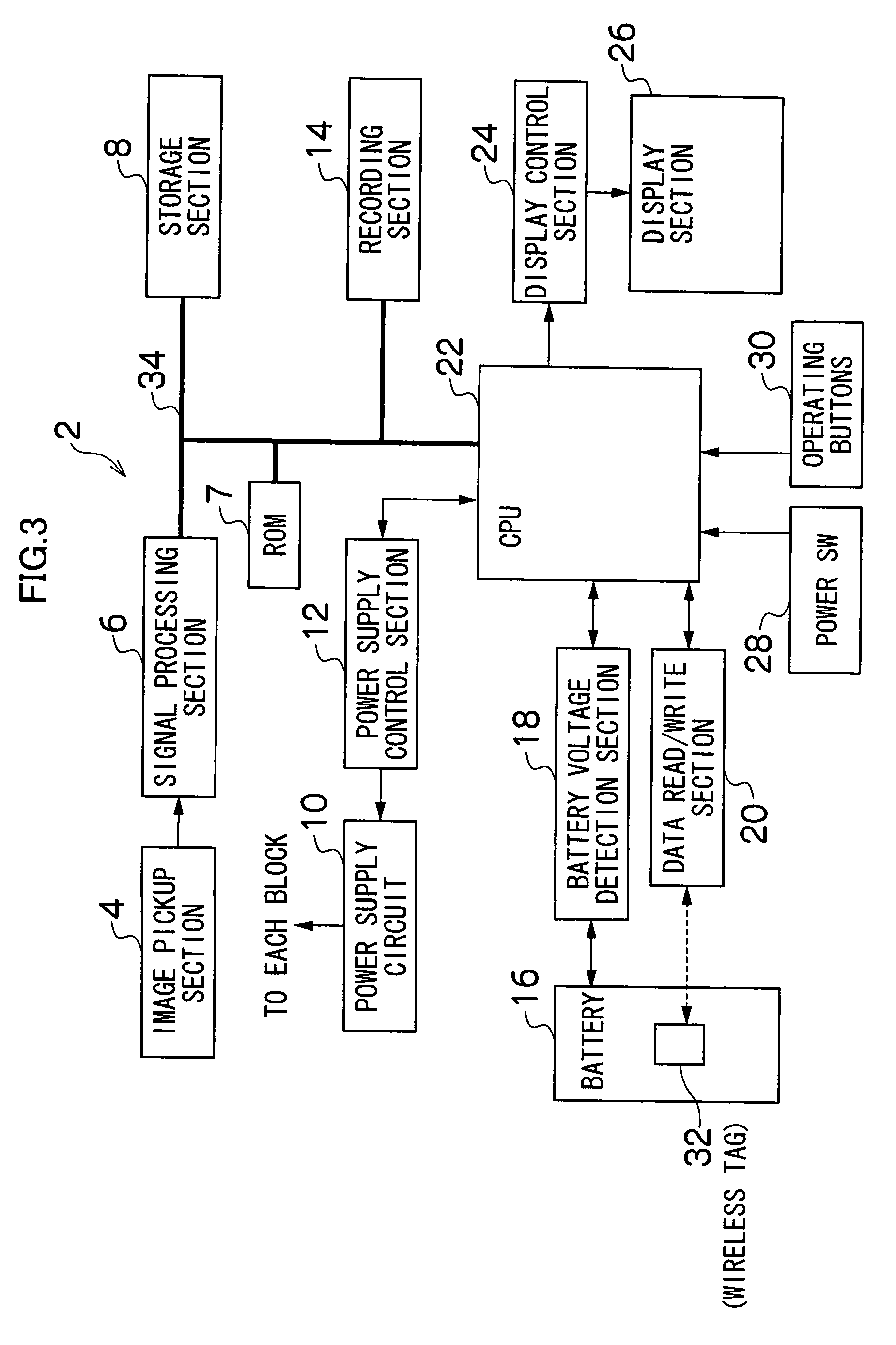
[0056]FIG. 3 is a block diagram of the digital camera 2 of the present invention.

[0057]The camera 2 is a digital camera having image recording and reproduction functions. A central processing unit (CPU) 22 performs overall control of the operation of the entire camera 2. The CPU 22 functions as a control device which controls the camera system in accordance with a predetermined program and as an warning generation device which generates battery remaining energy warning information according to a kind of battery identified.

[0058]Various sorts of data necessary for the program and control executed by the CPU 22 are stored in a read-only memory (ROM) 7 connected to the CPU 22 via a bus 34. The ROM 7, which is a nonvolatile storage device, may be non-rewritable one or a rewritable one such as an electrically programmable erasable read-only memory (EEPROM).

[0059]A storage section 8 is used as a program loading area and a computation work area for the CPU 22 and is also used as an area fo...

second embodiment

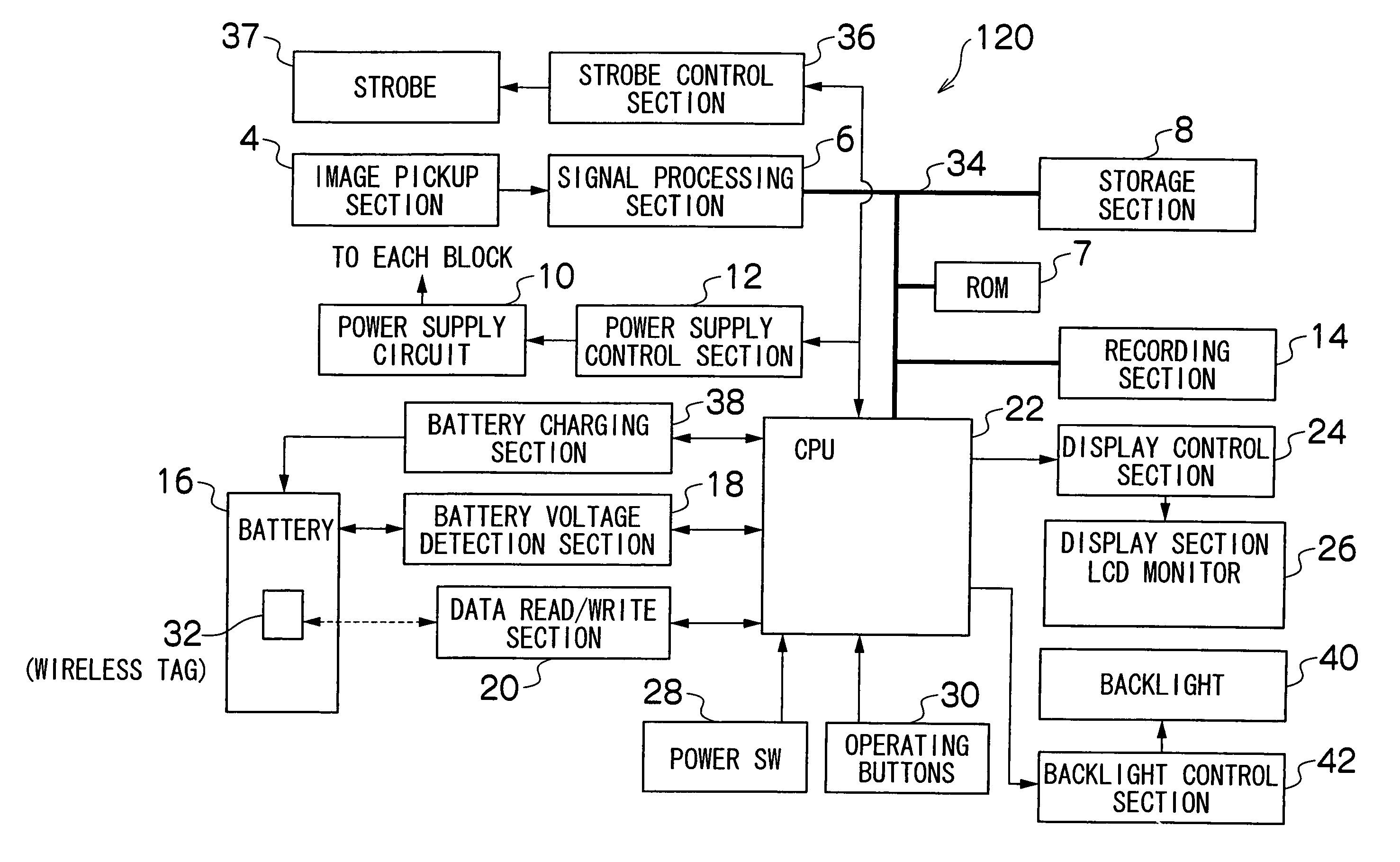
[0109]FIG. 7 is a block diagram showing the digital camera 120 of the present invention.

[0110]The camera 120 is a digital camera having image recording and reproduction functions. A central processing unit (CPU) 22 performs overall control of the operation of the entire camera 120. The CPU 22 functions as a control device which controls the camera system in accordance with a predetermined program and as a control command generation device which performs such control as to reduce the power consumption of the digital camera 120 according to a kind of battery identified.

[0111]The program and control executed by the CPU 22, various sorts of data necessary for control, etc., are stored in a ROM 7 connected to the CPU 22 via a bus 34.

[0112]A storage section 8 is used as a program loading area and a computation work area for the CPU 22 and is also used as an area for temporarily storing image data and audio data.

[0113]The camera 120 is provided with operating buttons 30 including a mode se...

third embodiment

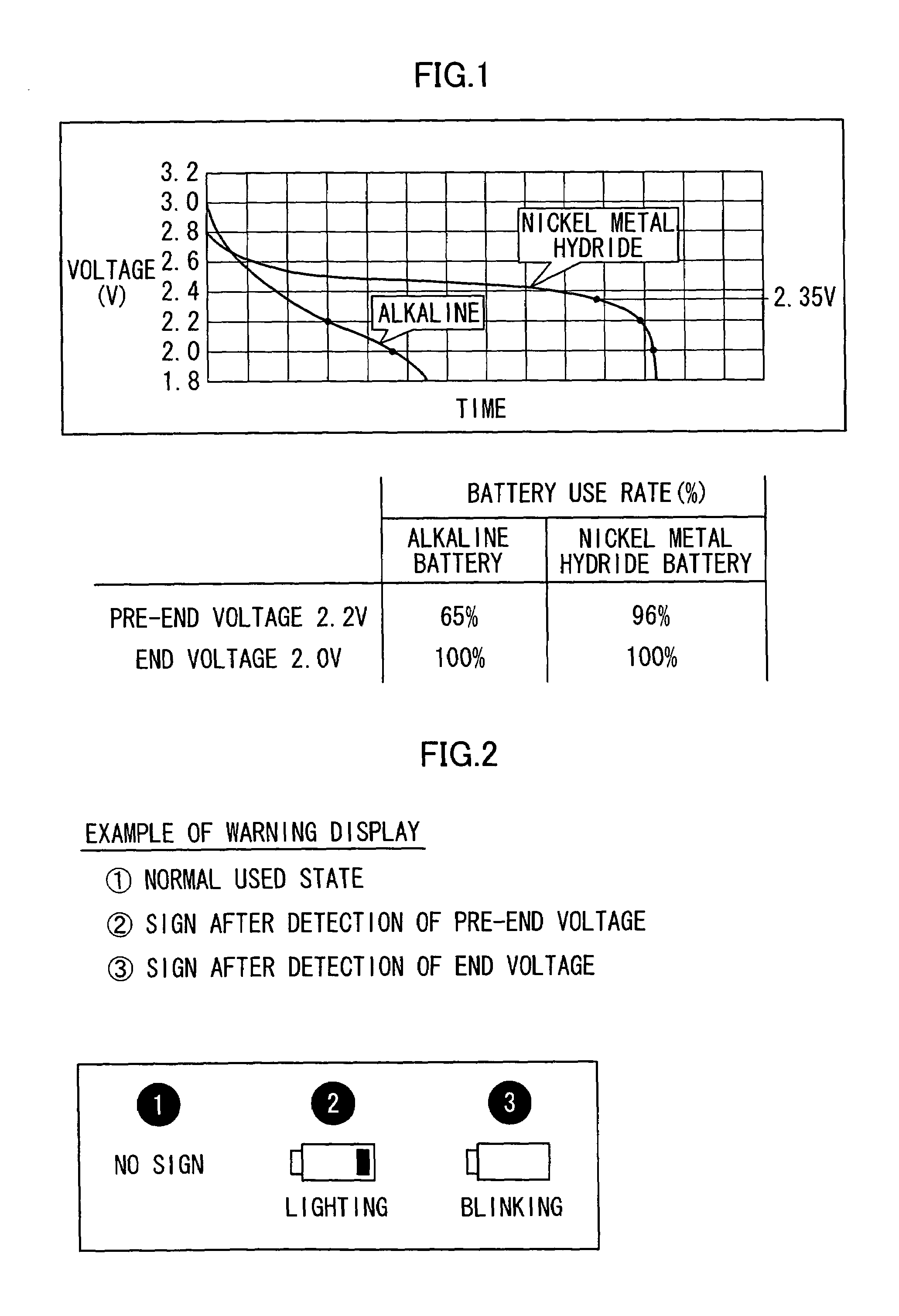
[0157]In the third embodiment, an warning is automatically displayed on the digital camera according to the kind of battery and the number of charging cycles to enable a user to easily grasp the battery use limit and to prepare a new battery without mistaking a degraded state of the battery for a malfunction of the camera. In a case where the digital camera is used until the battery use limit is exceeded, a low-power-consumption setting is made to increase the operating time of the battery and to enable use of the battery for a while even after the user has forgotten to change the battery.

[0158]In the description of the third embodiment, three methods have been mentioned as a power control setting in step 260. However, a combination of two of the above-described three methods may be used.

[0159]A setting may also be made according to a user's preference with respect to step 260 such that the setting is not automatically changed in step 260.

[0160]If information on the number of batter...


PUM

PropertyMeasurementUnit
voltageaaaaaaaaaa
voltageaaaaaaaaaa
voltageaaaaaaaaaa

Abstract

An electronic appliance has a data read / write section which reads information about a battery stored in a wireless tag provided in the battery, and a CPU which recognizes the read information about the battery and generates battery remaining energy warning information to be displayed on a display section according to the battery information. The battery remaining energy warning information according to the kind of the battery, the name of the manufacturer of the battery, etc., is generated and displayed to correctly and effectively inform a user of a remaining energy warning about the battery presently used.

Description

[0001]This Nonprovisional application claims priority under 35 U.S.C. § 119(a) on Patent Application No(s). 2003-101121; 2003-101122 and 2003-143571 filed in JAPAN on Apr. 4, 2003; Apr. 4, 2003 and May 21, 2003, the entire contents of which are hereby incorporated by reference.BACKGROUND OF THE INVENTION[0002]1. Field of the Invention[0003]The present invention relates to a portable electronic appliance and a battery and, more particularly, to a portable electronic appliance capable of using a battery as a power source and a battery capable of being used as a power source.[0004]2. Description of the Related Art[0005]Many of portable electronic appliances such as digital cameras are capable of operating on a detachable battery for their portability and use AA batteries which are immediately available. AA batteries include many kinds, e.g., manganese batteries, alkaline batteries and lithium batteries formed as primary batteries, and nickel-cadmium batteries and nickel metal hydride b...

Claims


Application Information

Patent Timeline
Patent Type & Authority Patents(United States)
IPC IPC(8): H01M10/46H02J7/02H02J7/00
CPCH02J7/0004H02J7/0009H02J7/0047H02J2007/006H02J7/00043H02J2207/30H02J7/00036H02J7/00047Y02P70/50H02J7/0048
Inventor KAWAGUCHI, RYUJIKUBOTA, MASAKATSUISHIHARA, ATSUHIKOKAWASUMI, SEIJI
Owner FUJIFILM CORP
Why Eureka
Try Eureka