Phase shifting and combining architecture for phased arrays

Active Publication Date: 2008-04-01
GLOBALFOUNDRIES US INC
View PDF11 Cites 18 Cited by
  • Summary
  • Abstract
  • Description
  • Claims
  • Application Information

AI Technical Summary

Benefits of technology

[0013]Principles of the invention provide impr

Problems solved by technology

These signals are then combined, where the signals add constructively for the desired direction and destructively for other directions.
More generally, for an N-element array, the phase shifter has to vary from αmin to αmin−(N−1)π. Such a large phase-shift range can be difficult to achieve.
Without these amplifiers, the directivity of the array will suffer.
This comes with the penalty of having to generate very precise phase shifts and amplitude balance at high frequencies.
The key drawback of digital beamforming

Method used


Image

  • Phase shifting and combining architecture for phased arrays
  • Phase shifting and combining architecture for phased arrays
  • Phase shifting and combining architecture for phased arrays

Examples


Embodiment Construction

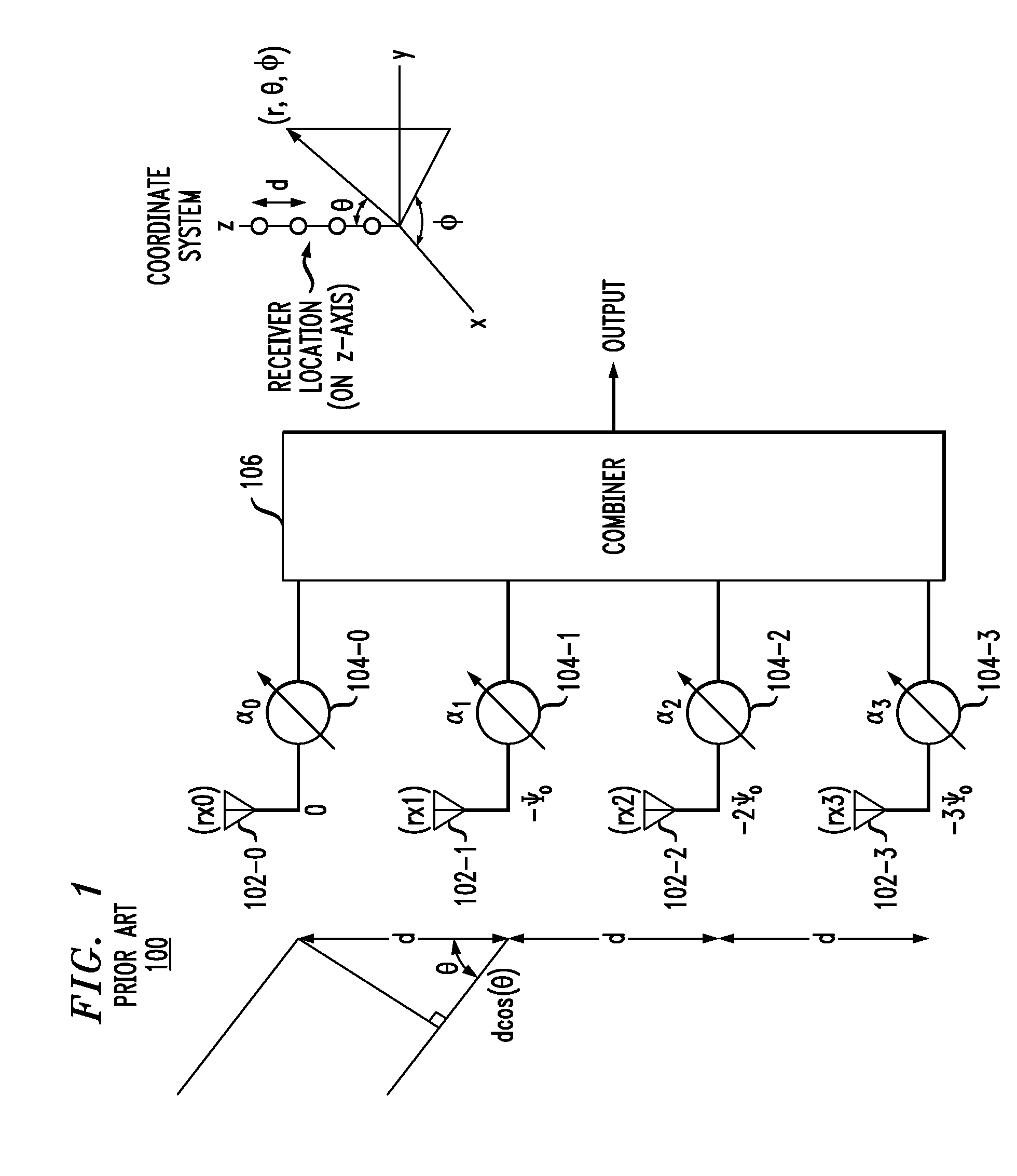
[0026]It is to be appreciated that while illustrative principles of the invention are described herein with regard to an N-element linear array for a receiver, the principles apply to transmitters as well.

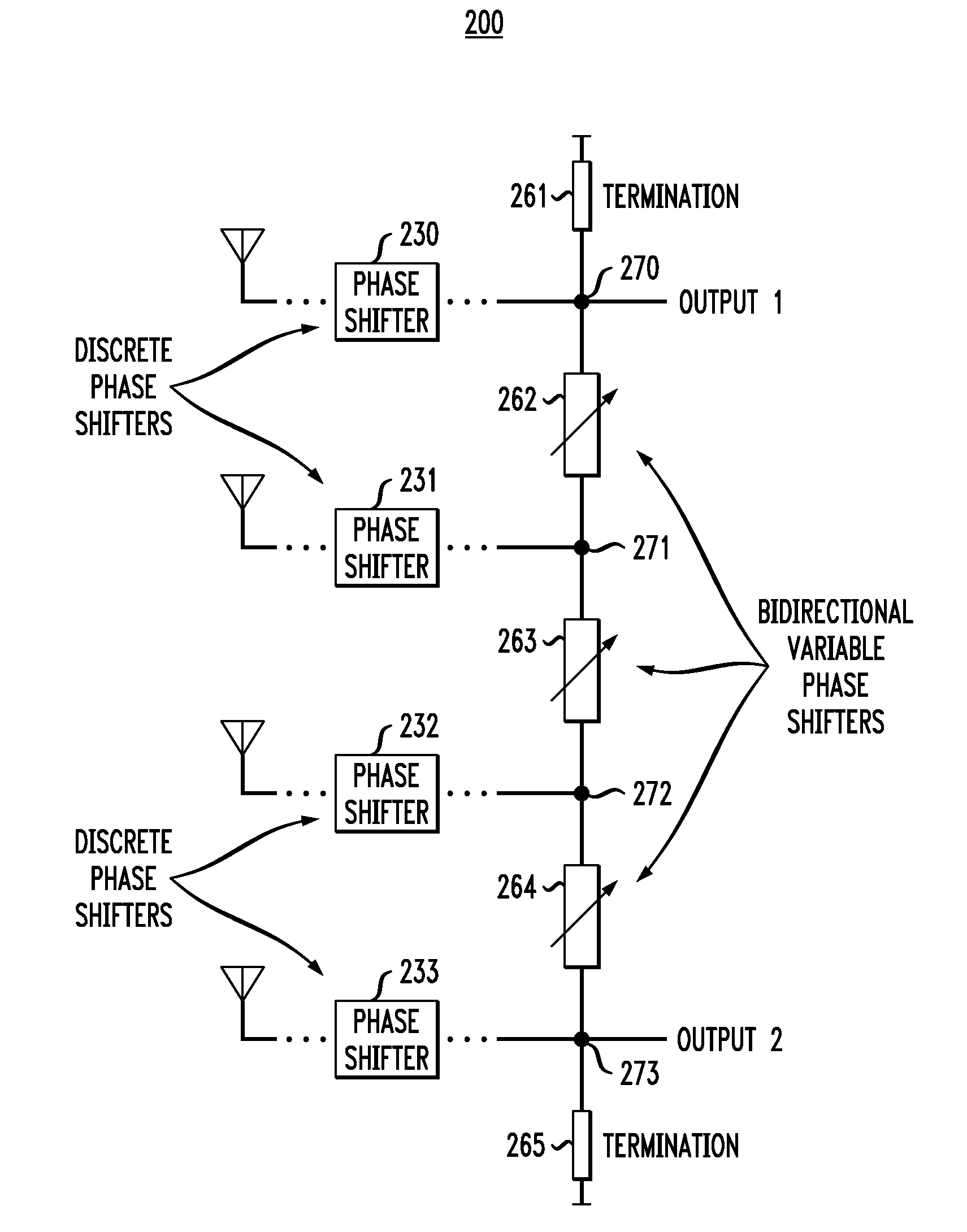
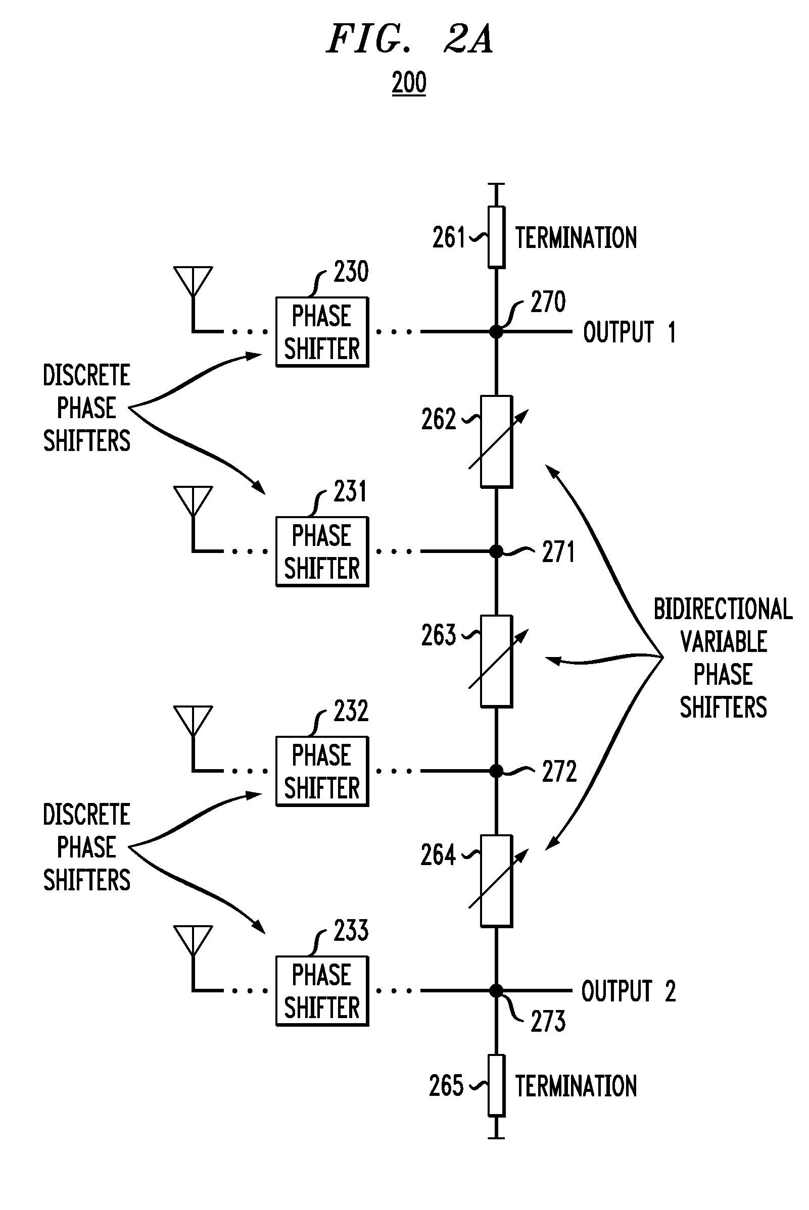
[0027]FIG. 2A generally depicts one embodiment of a 4-element linear phased array, applicable to both receivers and transmitters. The main functional components of phased array architecture 200 include parallel discrete phase shifters 230, 231, 232 and 233, connected to nodes 270, 271, 272 and 273, respectively. Furthermore, the inventive architecture provides for inserting bidirectional variable phase shifters (VPS) 262, 263 and 264 between adjacent nodes 270 and 271; 271 and 272; and 272 and 273, respectively. Furthermore, termination impedances 261 and 265 are attached to nodes 270 and 273, respectively, and these nodes are the two outputs from the linear phased array. Note that while these nodes serve as outputs for a receiver implementation, it is to be understood that they ma...


PUM


Abstract

Improved phased array techniques and architectures are provided. For example, a linear phased array includes N discrete phase shifters and N−1 variable phase shifters, wherein the N−1 variable phase shifters are respectively coupled between adjacent output nodes of the N discrete phase shifters such that the N discrete phase shifters reduce an amount of continuous phase shift provided by the N−1 variable phase shifters. Each of the N discrete phase shifters may select between two or more discrete phase shifts. The N discrete phase shifters also preferably eliminate a need for a variable termination impedance in the linear phased array.

Description

STATEMENT OF GOVERNMENT RIGHTS[0001]This invention was made with Government support under Contract No.: N66001-02-C-8014 awarded by the Defense Advanced Research Projects Agency. The Government has certain rights in this invention.FIELD OF THE INVENTION[0002]The present invention generally relates to signal transmitting and receiving systems and, more particularly, to phased arrays used in such systems.BACKGROUND OF THE INVENTION[0003]A brief overview of phased arrays is provided in this section in a context which illustrates system requirements and existing implementations. In this section, we will focus primarily on the receiver, though the concepts described also can be applied to the transmitter.[0004]Phased arrays are used to electronically steer the direction of maximum sensitivity of a receiver, providing spatial selectivity or equivalently higher antenna gain. Phased arrays find use in many different wireless applications, including but not limited to RADAR and data communic...

Claims


Application Information

Patent Timeline
IPC IPC(8): H01Q3/00
CPCH01Q3/30H01Q21/0037H01P1/18
Inventor FLOYD, BRIAN ALLANNATARAJAN, ARUN SRIDHAR
Owner GLOBALFOUNDRIES US INC
Why Eureka
Try Eureka