System and method for correcting multiple axis displacement distortion

a multiple axis displacement and correction system technology, applied in image enhancement, instruments, printers, etc., can solve problems such as keystone distortion, mechanical prior art system generally lack of flexibility, and compensation is essentially limited to correcting one axis

Inactive Publication Date: 2008-04-01
GEO SEMICONDUCTOR INC
View PDF19 Cites 69 Cited by
  • Summary
  • Abstract
  • Description
  • Claims
  • Application Information

AI Technical Summary

Problems solved by technology

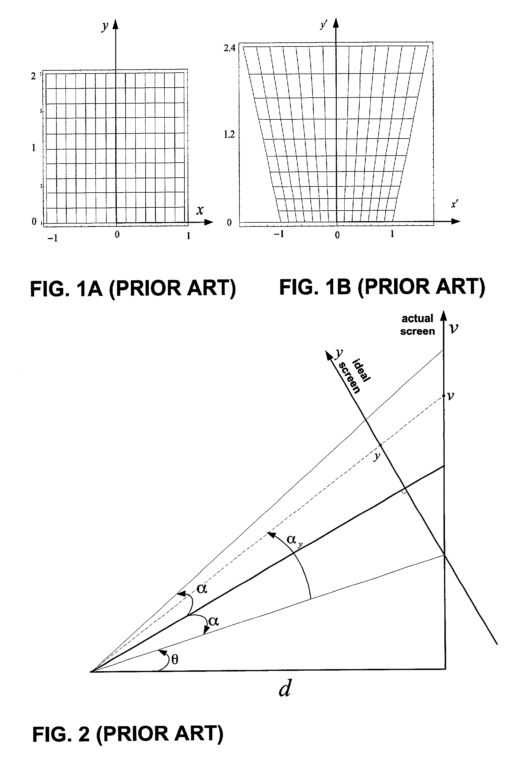
As is conventionally known, projecting an image onto a plane at an angle of elevation or depression causes keystone distortion.
This is a common problem for projections where projectors are positioned below the screen to project upwards to the screen.
However, such mechanical prior art system generally lack flexibility in that compensation is essentially limited to correcting one axis, usually along the vertical axis.
This system is, however, only effective for dist

Method used


Image

  • System and method for correcting multiple axis displacement distortion
  • System and method for correcting multiple axis displacement distortion
  • System and method for correcting multiple axis displacement distortion

Examples


Embodiment Construction

[0060]FIG. 5 illustrates an example projection correction system 10, built in accordance with the present invention. Specifically, correction system 10 identifies various projection distortion parameters, generates an inverse transformation corresponding to the projection parameters, receives and pre-distorts input image data by applying the inverse transformation, and outputs pre-distorted image data, which will appear distortion-free once projected on a screen (not shown). Specifically, correction system 10 includes a projection parameter module 12, a computational module 14, an image processor 16, a projection orientation detector 18, and a warp coefficient database 20.

[0061]The projector orientation detector 18 may be any automatic device that captures the relative orientation between the projector and the projection screen. While it is preferred that the user manually inputs the orientation to the system and the focal length of the optical system, although it should be understo...


PUM


Abstract

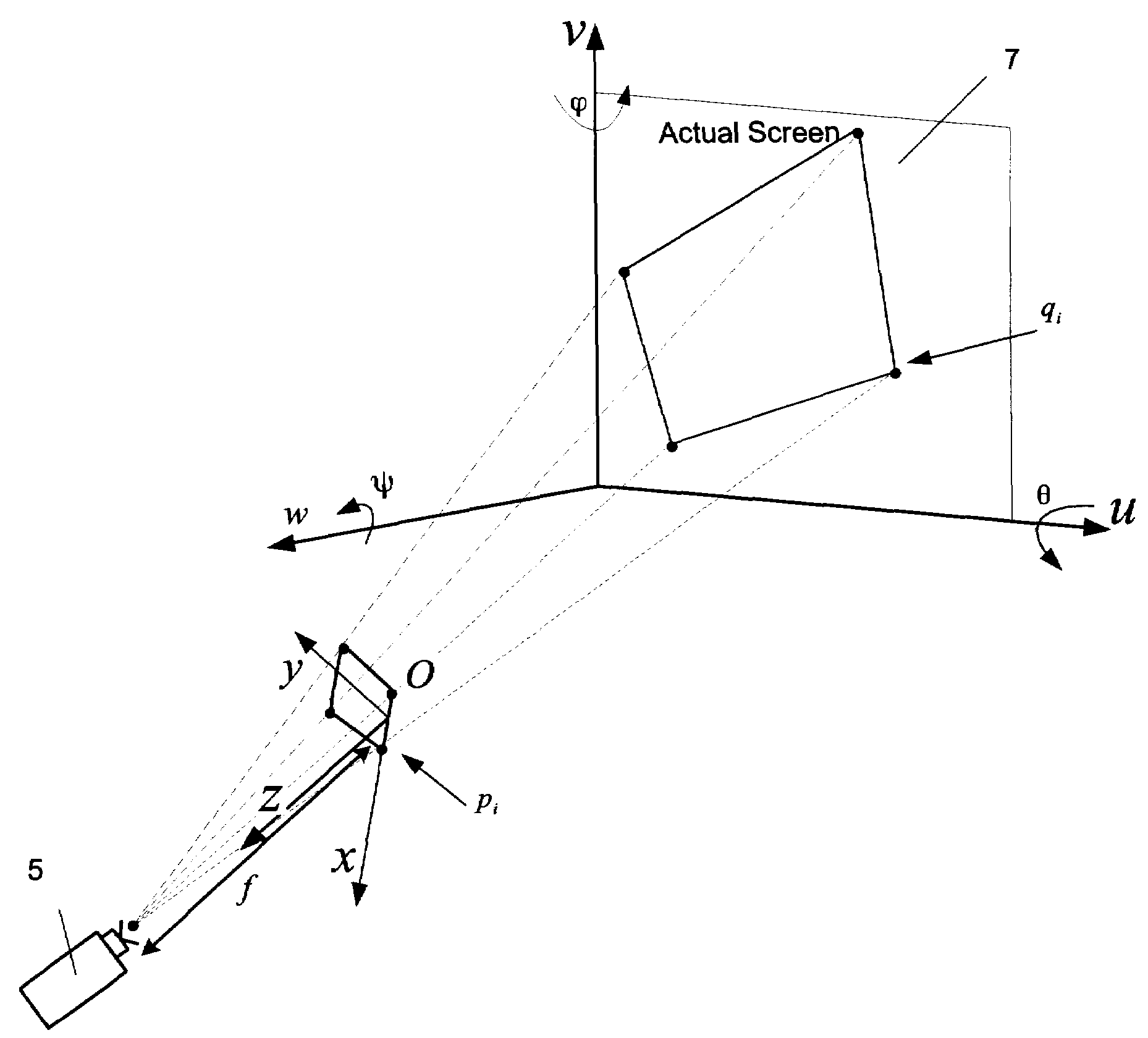
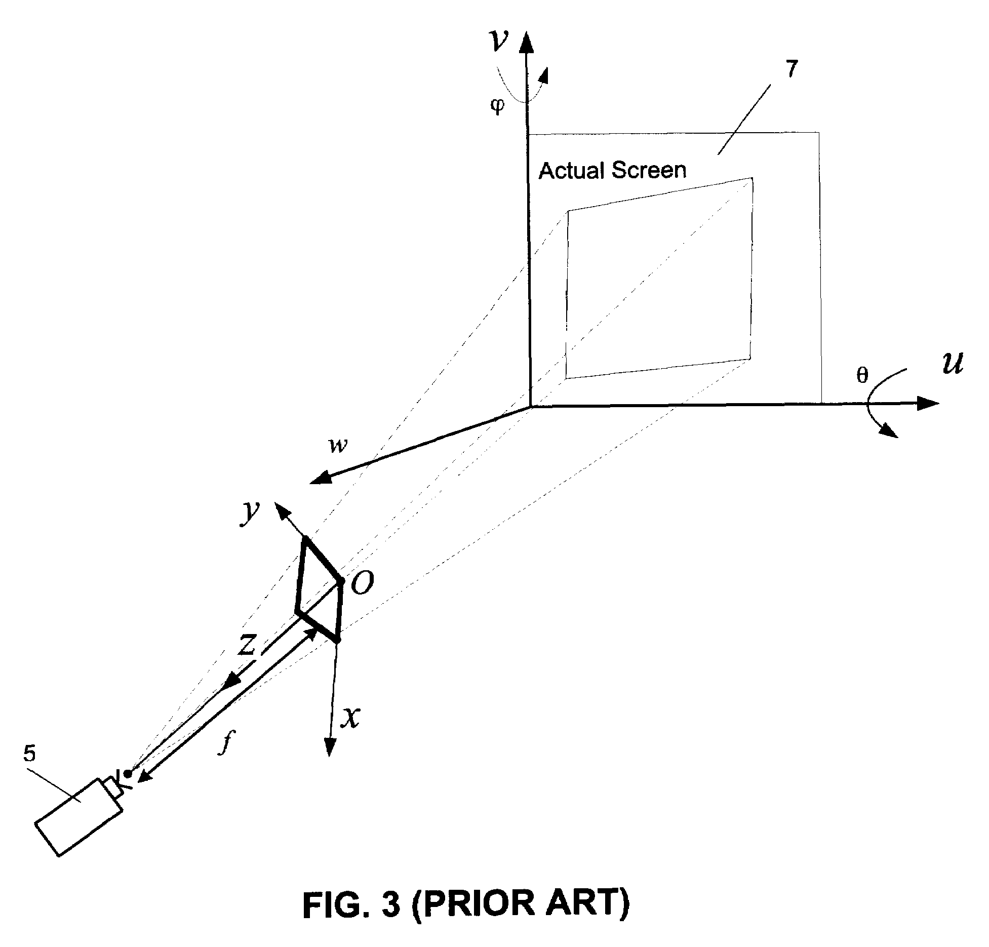
A system and method for correcting distortion in projected images caused by the projection of an input image by a projector lens onto a projection screen having a surface that is not orthogonal to the projection axis of the projector. Projection parameters including the focal length of the projector lens and the angles that represent the pan, tilt and roll angle of the projector are obtained. Then the projected area and the best viewable rectangular area that fits within said projected area is determined. The distortion is then characterized by using a distortion transformation which corresponds to the transformation that exists between the vertices of the best viewable rectangular area and the corresponding vertices of the projected area. Finally, the distortion transformation is inverted and applied to input image to obtain a distortion free projected image.

Description

[0001]This application claims priority from U.S. Provisional Application No. 60 / 297,241 filed Jun. 12, 2001.FIELD OF THE INVENTION[0002]This invention relates to digital image processing and spatial image transformation, and in particular, to the correction of multiple axial displacement distortion in images.BACKGROUND OF THE INVENTION[0003]As is conventionally known, projecting an image onto a plane at an angle of elevation or depression causes keystone distortion. This is a common problem for projections where projectors are positioned below the screen to project upwards to the screen. The resulting images are generally known as having a “top-heavy” appearance.[0004]FIGS. 1A, 1B and 2 illustrate the effect of off-axis projection. Specifically, FIG. 2 shows a projection configuration of a projector 5 and a screen 7 for the square image of FIG. 1. The ideal projection shown in FIG. 1A is from the ideal screen shown positioned along the y-axis and the top-heavy distorted projection s...

Claims


Application Information

Patent Timeline
IPC IPC(8): G06K9/40G02B27/00G03B27/68G06T3/00G06T11/80H04N5/74H04N9/31H04N17/00
CPCG02B27/0025G03B27/68G06T3/00G06T5/006H04N5/74H04N9/3185H04N9/3194H04N9/3197G06T2207/20021
Inventor KARUTA, BONAVENTURELEE, LOUIE
Owner GEO SEMICONDUCTOR INC
Why Eureka
Try Eureka