Snowmobile with improved air intake structure

a technology of air intake and snowmobile, which is applied in the field of snowmobile, can solve the problems of limited space between the engine and the rider, difficulty in concentrating the mass of the engine and the mass of the rider, and limitation in reducing the moment of inertia of the vehicle, so as to enhance the pleasantness of the traveling experience and reduce the intervening space

Inactive Publication Date: 2008-04-08
HONDA MOTOR CO LTD
View PDF15 Cites 13 Cited by
  • Summary
  • Abstract
  • Description
  • Claims
  • Application Information

AI Technical Summary

Benefits of technology

[0010]Accordingly, it is an object of the present invention to reduce the intervening space between an engine and a rider, to concentrate the masses of the various vehicle components, and to enhance the pleasantness of the traveling experience.
[0012]According to the first aspect of the invention, the cylinder of the engine is inclined rearwards. As a result, the center of gravity of the engine is disposed nearer to the rear side of the vehicle body. By using the construction in which the steering shaft is provided on the front side of the engine in addition to the rearward inclination of the engine, it is possible to lower the center of gravity of the engine, and to set the center of gravity of the vehicle body as a whole close to the center of the vehicle body. Therefore, the center of gravity of the vehicle body is concentrated in the vicinity of the vehicle body center, and the turning performance of the snowmobile is enhanced.
[0014]According to the second aspect of the invention, the throttle body is integrally provided with the injector for injecting the fuel, and the injector is provided on the upper side of the throttle body. As a result, gas stagnation of the fuel is prevented. In addition, the injector is more easily mounted to the throttle body.
[0016]According to the third aspect of the invention, the upper surface of the upper chamber is provided with the maintenance lid, so that it is possible to easily check the condition of the air-filtering element, and to easily detach and attach the air-filtering element.
[0022]According to the sixth aspect of the invention, the intake pipes are attached to the air cleaner case via the set plate, so that it is unnecessary to prepare individual fastening members or the like for attaching each intake pipe, and the set plate is used in place of the individual fastening members or the like. As a result, the number of required fastening members is reduced.
[0024]According to the seventh aspect of the invention, the set plate is provided with the slit portions for inserting the projection piece portions therein. The intake pipes are positioned and fixed to the air cleaner case by turning the intake pipes by a predetermined angle relative to the set plate, so that the operation for positioning and fixing the intake pipes to the air cleaner case is easily accomplished. As a result, the number of steps for assembling the intake pipes onto the air cleaner case is reduced.

Problems solved by technology

However, since the engine is laid out on the front side of the steering shaft, and the rider is seated on the rear side of the steering shaft, there is a limitation in reducing the space between the engine and the rider.
In other words, it is difficult to concentrate the mass of the engine and the mass of the rider toward the center of the vehicle body, and thus there is a limitation in reducing the moment of inertia of the vehicle.

Method used


Image

  • Snowmobile with improved air intake structure
  • Snowmobile with improved air intake structure
  • Snowmobile with improved air intake structure

Examples


Embodiment Construction

[0041]The best mode for carrying out the present invention will be described below, based on the accompanying drawings. In the figures and the following description, L is a subscript indicating the left as viewed from the driver, and R is a subscript indicating the right as viewed from the driver.

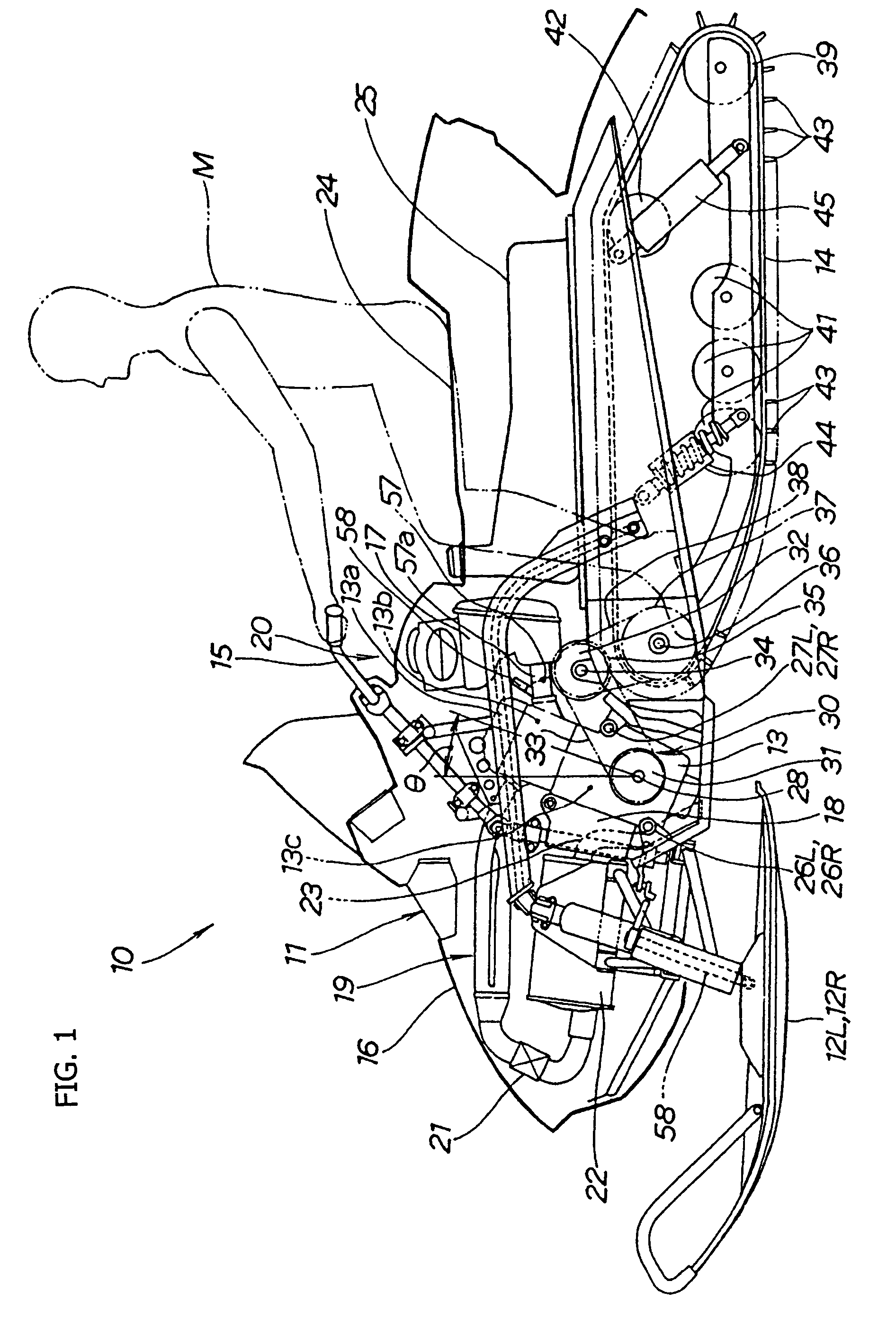
[0042]FIG. 1 is an overall side view of a snowmobile according to the present invention. The snowmobile 10 is a snow vehicle which comprises a left-right pair of skis 12L, 12R (12R is behind 12L, here and hereinafter), an engine 13, and a track belt 14, in this order from the front side toward the rear side of a vehicle body 11. The snowmobile travels by driving the track belt 14 by the power of the engine 13. The skis 12L, 12R are, steered by operating a steering handle 15. Further, a seat 24 for the rider is provided on the rear side of the engine 13. The engine 13 is provided at a front portion of the vehicle body. A fuel tank 25 is provided below the seat 24 and is elongated in the long...


PUM


Abstract

An improved snowmobile component layout structure includes an engine provided at front portion of the vehicle body, a cylinder head of the engine is inclined by an angle θ rearwards from a vertical axis, a steering shaft extends forwardly of the engine, and an air intake system, including an air cleaner, is provided at the rear side of the engine. In addition, a rider seat is provided on the rear side of the engine, and an elongated fuel tank is provided below the seat. The air cleaner has an improved disposition between the fuel tank and the engine. The inventive configuration narrows the spacing between an engine and a rider and concentrates mass to enhance turning performance.

Description

CROSS-REFERENCE TO RELATED APPLICATIONS[0001]The present invention claims priority under 35 USC 119 based on Japanese patent application No. 2004-069032, filed on Mar. 11, 2004, published on 22 Sep. 2005 as publication number 2005-254973. The subject matter of this priority documents is incorporated by reference herein.BACKGROUND OF THE INVENTION[0002]1. Field of the Invention[0003]The present invention relates to a snowmobile in which a steering shaft is provided on the front side of an engine and an air intake system, including an air cleaner, is laid out on the rear side of the engine.[0004]2. Description of the Background Art[0005]Conventionally, there are known snowmobiles in which a steering shaft is provided on the rear side of an engine, and an air intake system is disposed between the engine and the steering shaft. For example, this configuration is disclosed in Japanese Patent Laid-open No. 2002-364468 (especially FIG. 1 thereof).[0006]In Japanese Patent Laid-open No. 2002...

Claims


Application Information

Patent Timeline
Patent Type & Authority Patents(United States)
IPC IPC(8): B60K11/08B60K13/02F02M35/02B62J99/00B62D55/07B62M27/02F02M35/024F02M35/10F02M35/16
CPCB62M27/02F02M35/108F02M35/162B62M2027/023F02M35/112
Inventor ABE, TOMOHISAYAMADA, KOZOHOI, YOSUKE
Owner HONDA MOTOR CO LTD
Why Eureka
Try Eureka