
Tire vulcanizing apparatus

a technology of vulcanizing apparatus and vulcanizing plate, which is applied in the direction of belts, tires, domestic applications, etc., can solve the problems of large amount of time and labor required for machining and the inability to secure precision, so as to facilitate the fabrication and attachment of adjustment plates, prevent local wear and the like of segments and upper and lower circular plates

Active Publication Date: 2008-04-08
MITSUBISHI HEAVY IND MACHINERY SYST LTD
View PDF6 Cites 14 Cited by
  • Summary
  • Abstract
  • Description
  • Claims
  • Application Information

AI Technical Summary

Benefits of technology

[0011]An object of the present invention is to solve the problems as described above in the conventional tire vulcanizing apparatuses, and to make it possible to ensure, with a simple structure, that the dimensional accuracy between the upper and lower circular plates be maintained.
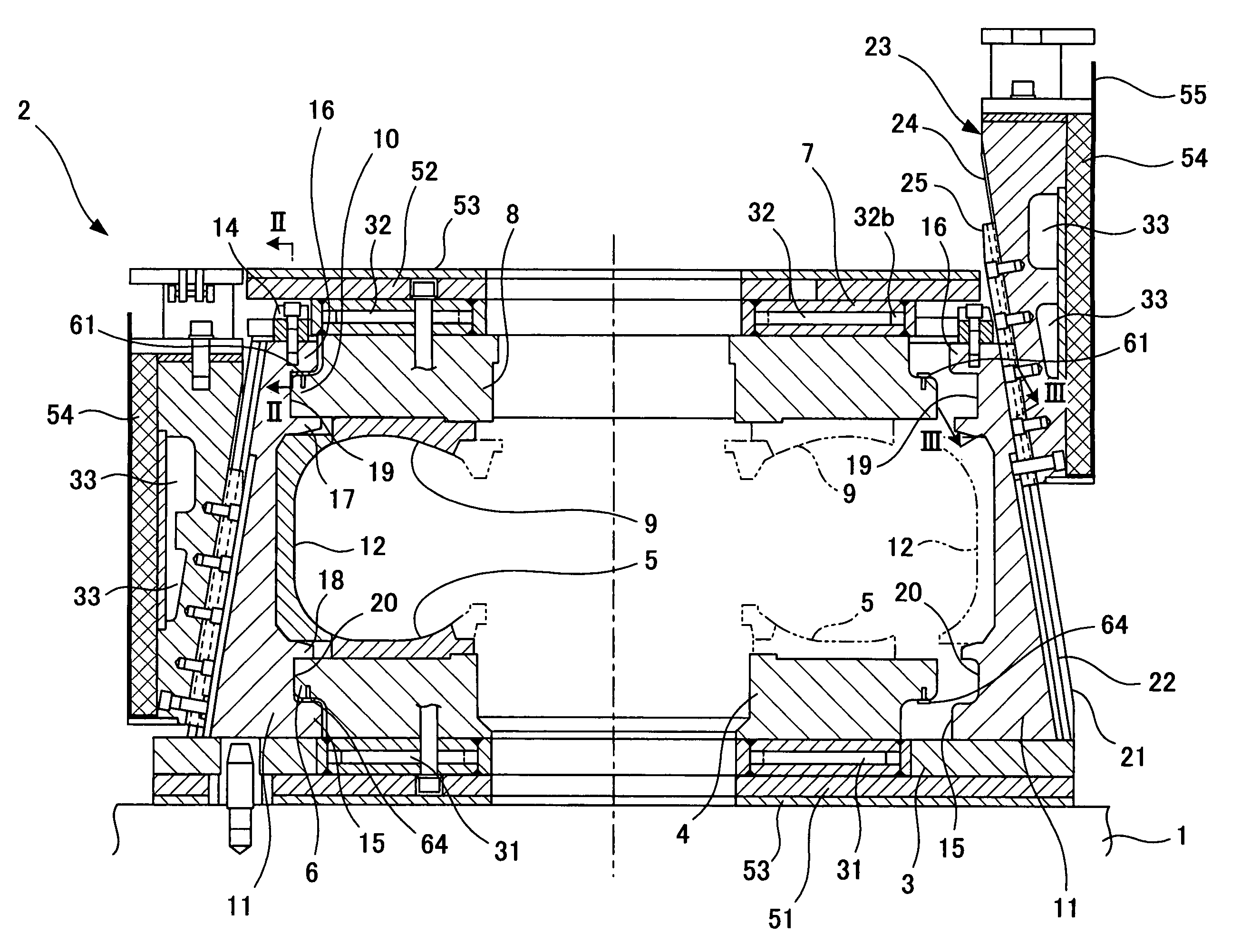
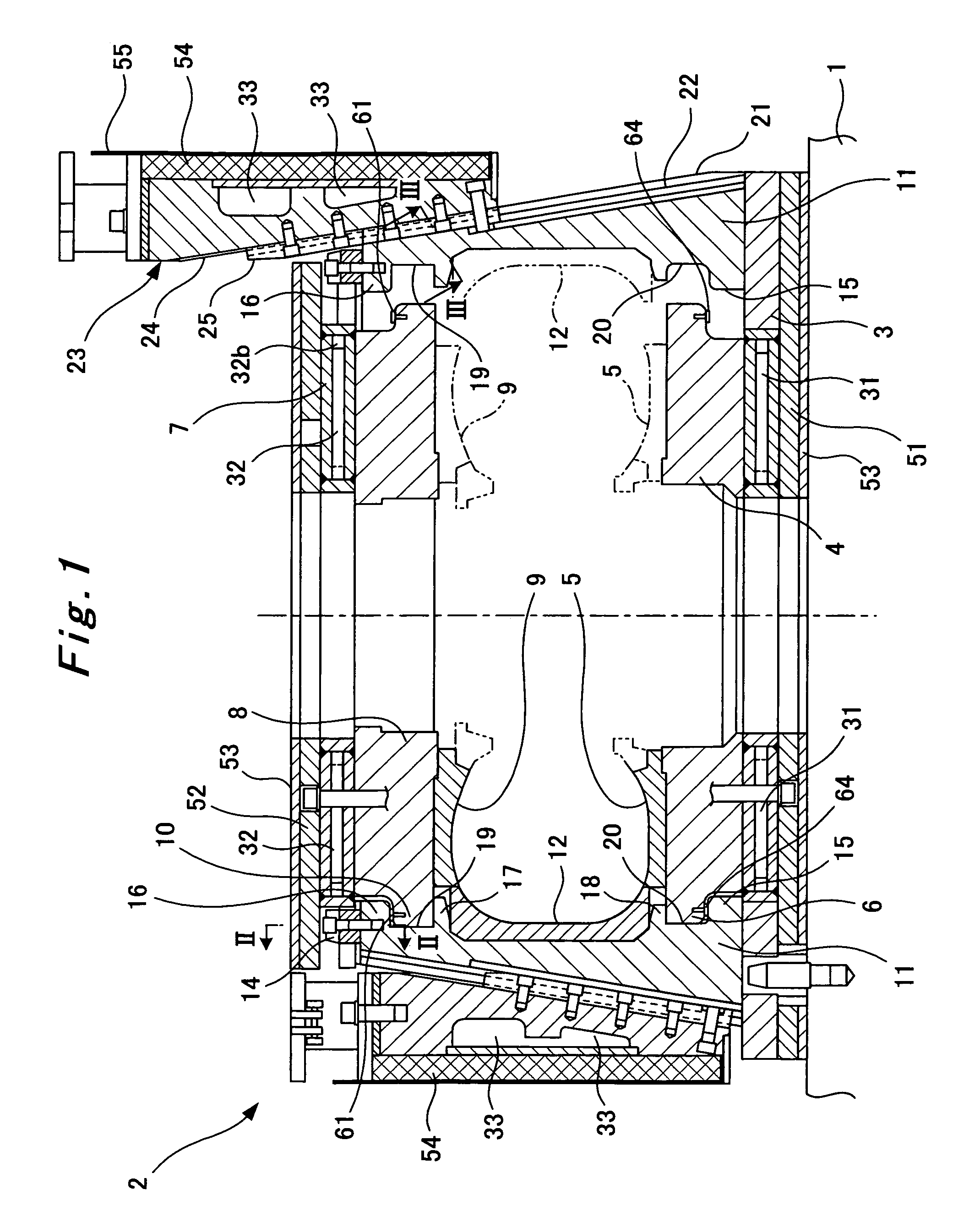
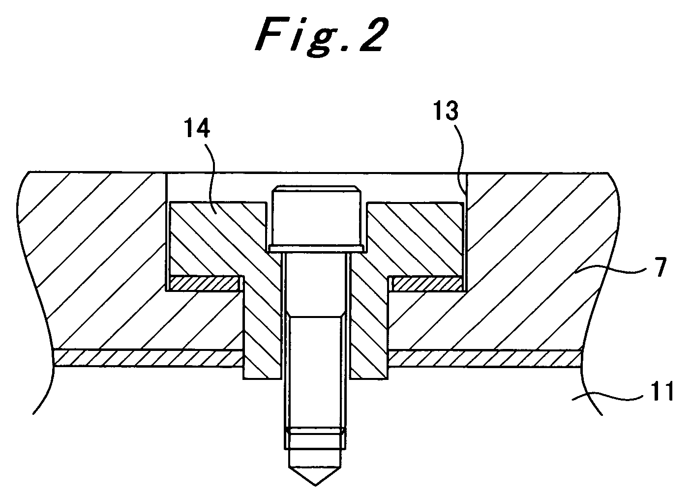
[0015]With the tire vulcanizing apparatus according to the first aspect, the adjustment plates are provided: to the interfaces between the lug portions of the segments and the protrusions of the upper and lower circular plates. Thereby, the dimensional accuracy between the upper and lower circular plates during pressurized vulcanization is maintained. Accordingly, the distance between the upper and lower circular plates can be maintained precisely, and relatively easily. Eventually, this makes it possible to manufacture tires having higher precision quality as final products than otherwise. Additionally, it becomes unnecessary to machine, with high precision, contact portions of the upper circular plate and each of corresponding one of the lug portions with each other, and contact portions of the lower circular plate and each of corresponding one of the lug portions with each other. Accordingly, a reduction in time required for the machining, and in manufacturing costs can be pursued. Furthermore, by performing maintenance on the adjustment plates, it is possible to perform precision adjustment and precision maintenance on the distance between surfaces to which the upper and lower sidewall dies are attached, respectively. When any one of the adjustment plates has worn, all that is required is to replace the worn adjustment plate with new one. For this reason, maintenance with high precision can be made inexpensively as well as easily.
[0017]With the tire vulcanizing apparatus according to the third aspect, fabrication and attachment of the adjustment plates can be facilitated because the adjustment plates are separated from one another. Additionally, local wear and the like of the segments and the upper and lower circular plates can be prevented by setting a separating position between each adjacent two of the separate plates corresponding to a gap between some adjacent two of the segments.

Problems solved by technology

For this reason, there has been a problem that large amounts of time and labor are required for machining of the segments and the upper and lower circular plates.
Additionally, there has been a problem that wear and the like of these abutting portions make it impossible to secure the precision.

Method used


Image

  • Tire vulcanizing apparatus
  • Tire vulcanizing apparatus
  • Tire vulcanizing apparatus

Examples


Embodiment Construction

[0027]Hereinbelow, a tire vulcanizing apparatus according to the present invention will be described in detail based on an embodiment.

[0028]An apparatus main body of the tire vulcanizing apparatus is provided with a fixed base 1. A die container 2 as a self-locking container is formed on the base 1. A lower platen 3 is fixed to the base 1. The lower platen 3 is an annular circular plate serving as a base of the die container 2. A lower circular plate (a lower plate) 4 having an annular shape is attached concentrically to the lower platen 3. A lower sidewall die 5 is attached to an upper surface of the lower circular plate 4. The lower sidewall die 5 is a lower die for molding one of sidewalls of the tire. A protrusion 6 for a self-locking purpose is formed on an upper portion of an outer circumferential surface of the lower circular plate 4. Note that, an unillustrated central mechanism is installed in the central portion of the lower platen 3 and the lower circular plate 4, from th...


PUM

PropertyMeasurementUnit
length of timeaaaaaaaaaa
forcesaaaaaaaaaa
timeaaaaaaaaaa

Abstract

Disclosed is a tire vulcanizing apparatus including: upper and lower circular plates, to which sidewall dies for forming side portions of a tire are attached; respectively; and plural segments, to which tread dies separated as plural pieces for forming a tread portion of the tire are attached; respectively, in which apparatus, the upper and lower circular plates are held by engagement of lug portions, formed respectively on upper and lower portions of the segments, with protrusions on outer circumferential portions of the upper and lower circular plates so as to prevent the upper and lower circular plates from moving away from each other, the apparatus being constituted by providing adjustment plates, used for maintaining a measurement between the upper and lower circular plates, to an interface between the protrusion of each of the upper and lower circular plates and a corresponding one of the lug portions of each segment.

Description

RELATED APPLICATIONS[0001]The present application is based on, and claims priority from, Japanese Application Serial Number 2006-312352, filed Nov. 20, 2006, the disclosure of which is hereby incorporated by reference herein in its entirety.BACKGROUND OF THE INVENTION[0002]1. Field of the Invention[0003]The present invention relates to a tire vulcanizing apparatus for molding and vulcanizing a green tire.[0004]2. Description of the Related Art[0005]In manufacture of tires, a tire vulcanizing apparatus using a self-locking container has been known as an apparatus for molding and vulcanizing a green tire. Such a tire vulcanizing apparatus is disclosed in, for example, Japanese Patent Publication No. 2505675 and Japanese Patent Application Publication No. 2001-79850.[0006]As are described in these publications, in such a tire vulcanizing apparatus using a self-locking container, the self-locking container is a die container (a metal mold apparatus). The die container is a part for mold...

Claims


Application Information

Patent Timeline
Patent Type & Authority Patents(United States)
IPC IPC(8): B29C35/02
CPCB29C33/303B29D30/0629B29C35/02
Inventor HINENO, YOSHIKATSUMURAKAMI, TOSHIFUMI
Owner MITSUBISHI HEAVY IND MACHINERY SYST LTD
Learn More