Chilled water storage for milk cooling process

a technology of milk cooling and chilled water, which is applied in the field of liquid cooling process, can solve the problems of high energy consumption, costly operation of refrigeration equipment, and the failure of cooling process to achieve simplified cooling process fully, so as to ease the strain on the state

Inactive Publication Date: 2008-04-15
GRUBER DUANE A +1
View PDF33 Cites 6 Cited by
  • Summary
  • Abstract
  • Description
  • Claims
  • Application Information

AI Technical Summary

Benefits of technology

[0019]The present invention also extends to a chilled water storage for air conditioning process, which is a method for cooling the interior of a building while conserving energy during peak demand hours. The system chills water in a water chiller during the off-peak electrical demand hours, and then stores the water in an insulated tank until peak electrical demand hours. Because the water chiller uses the bulk of the electrical energy required for the system, running the chiller only during the off-peak hours saves money and reduces the peak hours burden for power companies.
[0024]After then passing through the pump, the chilled water now is directed by the second three-way valve into the heat exchanger line. The chilled water passes through the heat exchanger coils, allowing heat to transfer from the warmer air moving through the ventilation system. This causes the temperature of the water to rise as it exits the heat exchanger.
[0027]Accordingly, it is a principal object of this invention to provide a simplified process for cooling liquids during peak electrical demand periods with a coolant liquid that is chilled during off-peak electrical demand periods.
[0028]It is another object of this invention to provide a simplified process for cooling liquids so that the liquids are significantly cooled with little or no use of refrigeration units during peak electrical demand periods.
[0029]It is a further object of the invention to ease strains on a state's electrical power grid system in an economical and environmentally safe way.
[0032]It is an object of the invention to provide improved elements and arrangements thereof in a process for the purposes described which is inexpensive, dependable and fully effective in accomplishing its intended purposes.

Problems solved by technology
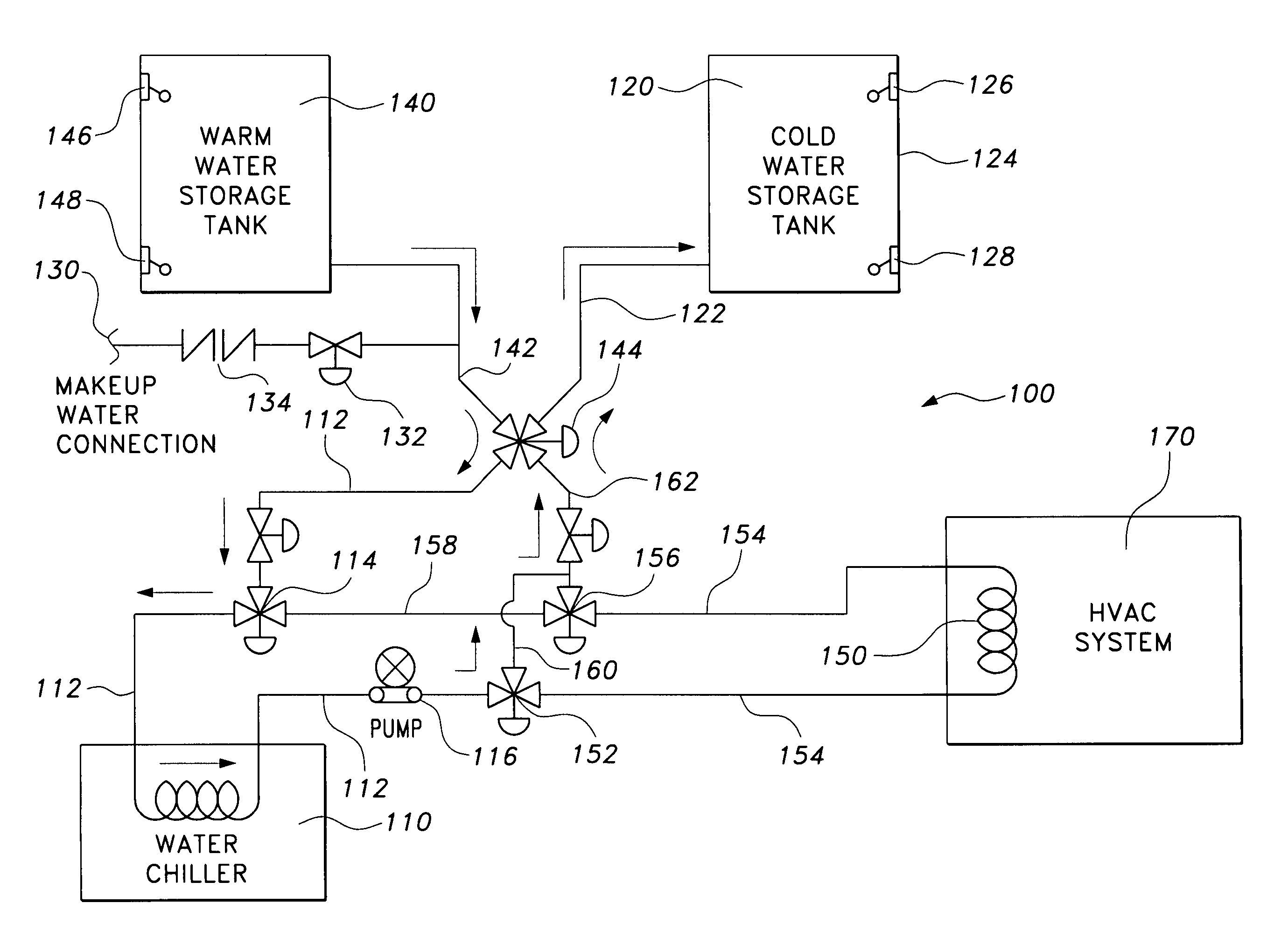
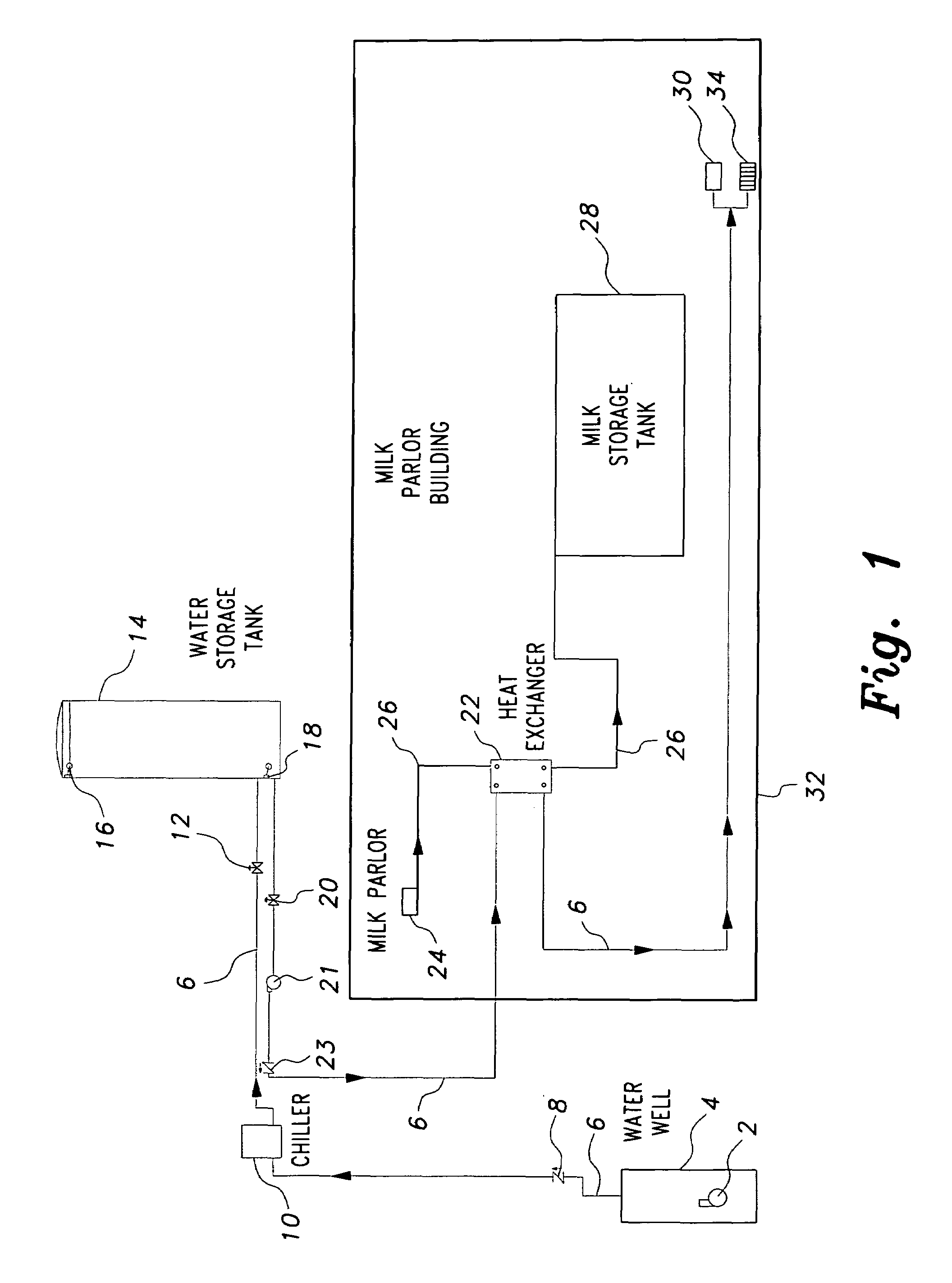
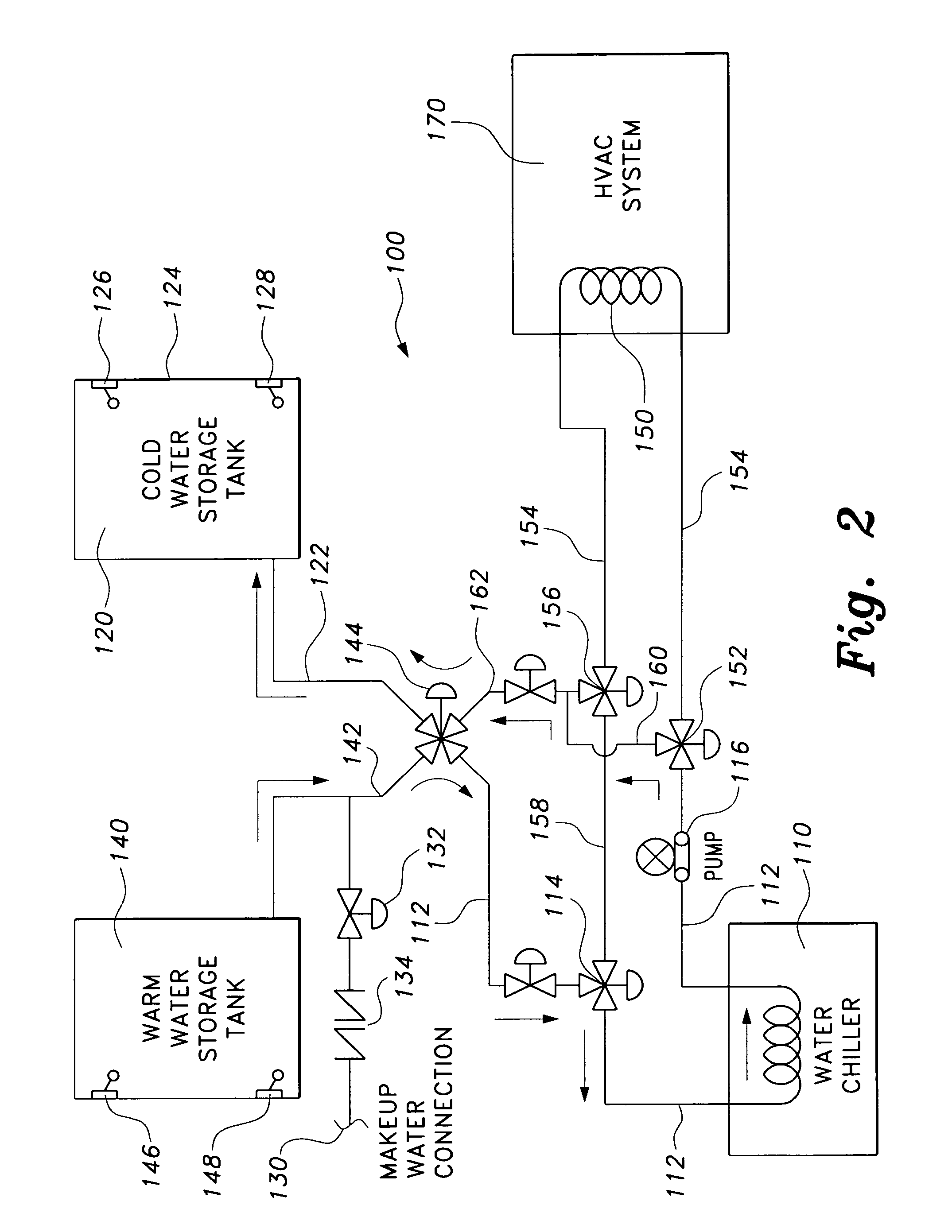
Consequently, in order to comply with state requirements pertaining to the cooling of milk, the majority of dairy farms operate costly refrigeration equipment on a 24-hour basis.
Related art cooling processes have failed to achieve a simplified cooling process which fully realizes the potential for increased energy efficiency by neglecting to incorporate use of thermal storage, a pre-cooling step, or an effective combination of both processes.
As the storage tank for the milk also serves as the cooling unit, this cooling process relies heavily on constant refrigeration and is subject to the drawbacks mentioned above associated with cooling systems which lack a separate pre-cooling phase before the milk is directed into the storage tank.
The re-cooling of the refrigerant requires a great deal of energy consumption.
First, power companies often charge more for energy used during peak hours, raising the cost of air-conditioning buildings during these hours.
Second, heavy air conditioning use over a highly populated area during peak hours can require more energy than some power plants are able to provide, creating a brown-out and shutting down the electrical supply for all users whose electricity is supplied by the overworked power plant.

Method used


Image

  • Chilled water storage for milk cooling process
  • Chilled water storage for milk cooling process
  • Chilled water storage for milk cooling process

Examples


example

[0043]The following example is illustrative of a possible application of the process of the present invention in a typical dairy farm and is not intended to be a limitation thereon. Table 1 depicts technical data for a hypothetical dairy farm. Table 2 depicts energy consumption in the dairy farm, which is based on a typical Time of Use (TOU) Rate Schedule. Table 3 depicts calculated energy savings which should be achievable using the present invention for the dairy farm based on the data provided in Tables 1 and 2.

[0044]

TABLE 1Approximate # of Cattle Milked per Day780-790Approximate Total Milk Production per Day6,960 gal / dayMilking Period / Cycle24 hoursMilk Temperature Leaving Cow101 deg / F.Milk Bulk Storage Temperature38 deg / F.Process Cooling Delta Temperature63 deg / F.Allowable Time to Achieve Process Delta4-5 minutesMilk Main Process Cooling Equipment Capacity30 ton DXrefrigerationVolume of Chilled Water to cool Gallon of Milk1.5 gal Water:1 gal Milk

[0045]

TABLE 2Energy ConsumptionEn...


PUM


Abstract

The chilled water storage for milk cooling process encompasses methods for chilling liquids during off peak hours for later consumption, including a method for cooling the interior of a building while conserving energy during peak demand hours, in which water is chilled in a water chiller during the off-peak electrical demand hours, then stored in an insulated tank until peak electrical demand hours. The stored cold water is then pumped through a heat exchanger connected to the ventilation system in the building to cool the air in the building. The water then passes into a second storage tank, where it is held until off-peak hours. A plurality of multi-directional valves automatically control the water flow through the system.

Description

CROSS-REFERENCE TO RELATED APPLICATIONS[0001]This is a continuation-in-part of my prior application Ser. No. 11 / 012,320, filed Dec. 16, 2004 now U.S. Pat. No. 7,222,492, which is a division of application Ser. No. 10 / 446,821, filed May 29, 2003, now issued Feb. 22, 2005 as U.S. Pat. No. 6,857,278, which claims the benefit of U.S. Provisional Patent Application Ser. No. 60 / 383,578, filed May 29, 2002.BACKGROUND OF THE INVENTION[0002]1. Field of the Invention[0003]The present invention relates to a cooling process for liquids, and specifically, a cooling process for liquids utilizing a coolant liquid that is chilled during off-peak electrical demand periods.[0004]2. Description of the Related Art[0005]Cow's milk as it comes from the cow has a temperature of over 90 degrees Fahrenheit. At this temperature, bacteria multiply with great rapidity. Thus, milking operations in most states are controlled by strict regulations, requiring for example, that bulk milk shall be cooled to 38-40 de...

Claims


Application Information

Patent Timeline
Patent Type & Authority Patents(United States)
IPC IPC(8): G05D23/32F25D17/02A01J9/04
CPCA01J9/04
Inventor GRUBER, DUANE A.GRUBER, MICHAEL E.
Owner GRUBER DUANE A
Why Eureka
Try Eureka