Two part oil or fluid drain plug with magnet

a technology of oil or fluid drain plugs and magnets, which is applied in the direction of crankshafts, machines/engines, auxilaries, etc., can solve the problems of difficult to reach or see, and achieve the effect of difficult installation

Active Publication Date: 2008-04-15
DORIAN GEORGE P
View PDF26 Cites 34 Cited by
  • Summary
  • Abstract
  • Description
  • Claims
  • Application Information

AI Technical Summary

Problems solved by technology

This is not a trivial matter, as many sump ports are difficult to reach or see from under a car.

Method used


Image

  • Two part oil or fluid drain plug with magnet
  • Two part oil or fluid drain plug with magnet
  • Two part oil or fluid drain plug with magnet

Examples


Embodiment Construction

[0050]My invention is a two part drain plug which I developed in light of, and to solve, the numerous issues and problems described in the above section entitled Description of Prior Art. I feel that my invention is the best practical way to solve those problems of any that I've seen in my research.

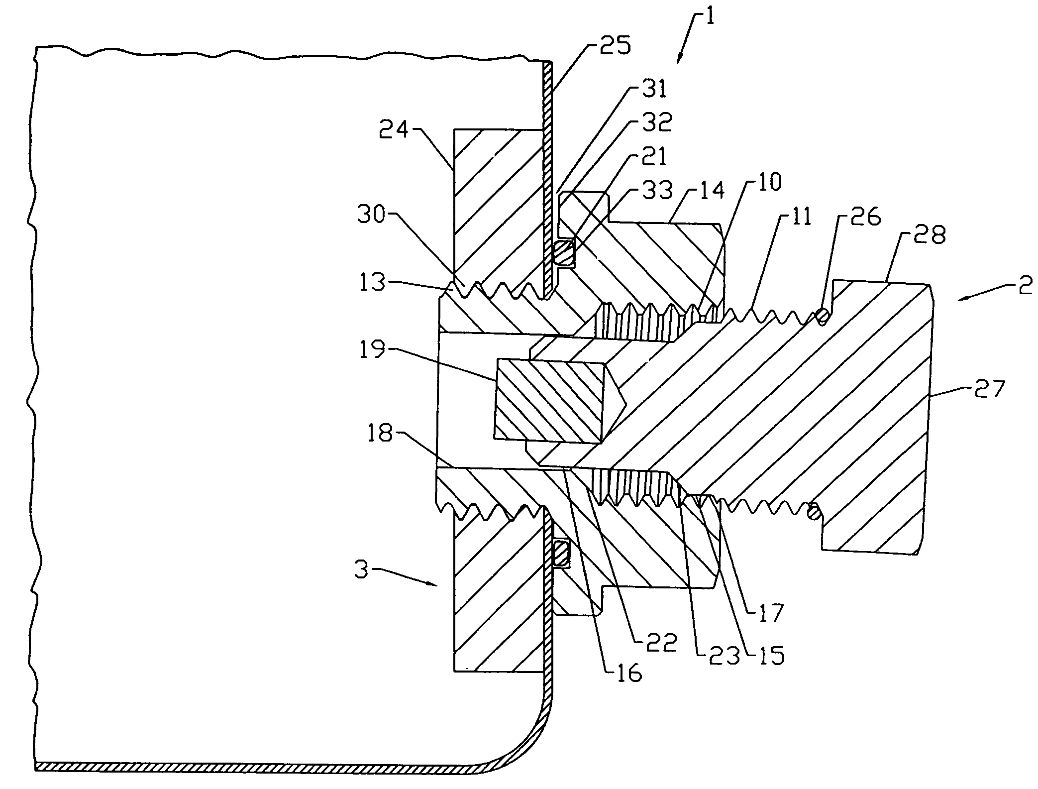
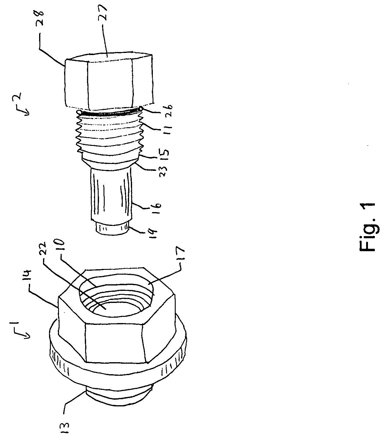
[0051]Referring to the accompanying drawings. FIG. 1 shows an isometric view of my invention, a two part drain plug. The two parts consist of a fitting body 1 and a plug body 2 that are machined from 303 Alloy Stainless Steel.

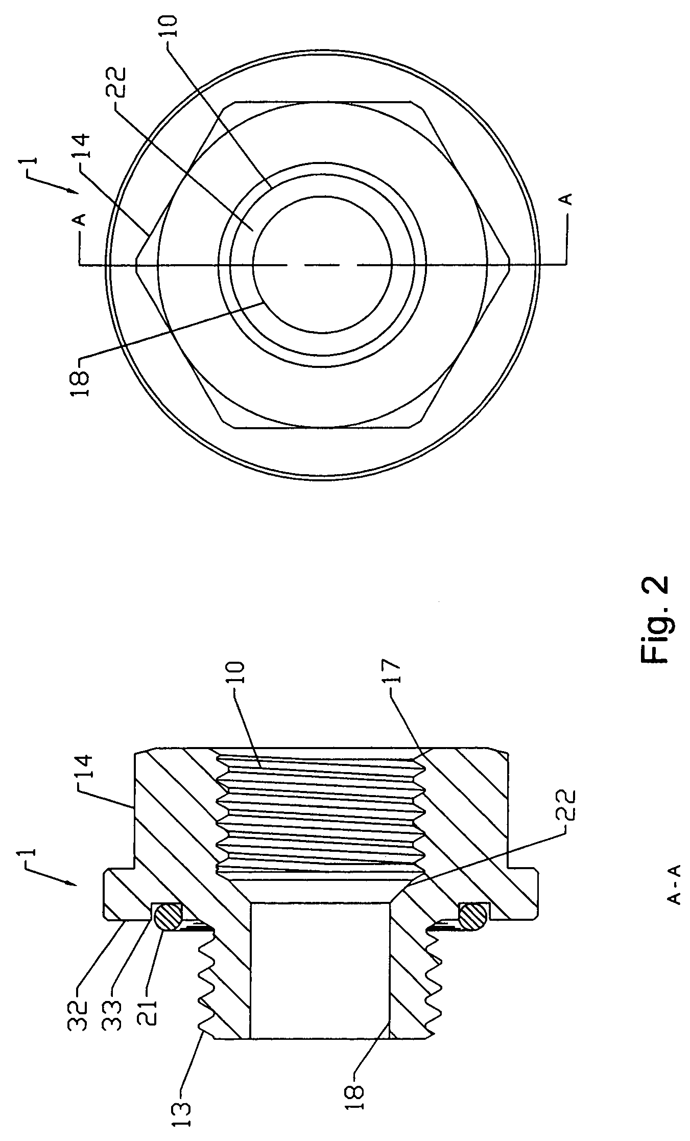
[0052]FIG. 2 is a drawing of the fitting body 1. The fitting body 1 consists of; an external threaded area 13 that screws into the oil port threads 30 of a sump 3: a face area 32 that makes contact with the outside surface of the sump 25: an area with wrench flats 14: an O-ring 21 to seal the fitting body 1 with the outside surface of the sump 25 to prevent oil 12 from leaking out: an axial bore with a smooth area 18, an conical shape 22 and an internal threaded area...


PUM


Abstract

A two part oil drain plug assembly facilitates the draining of oil or fluid from a sump, and its use prevents the threads of the sump, which may be an automotive oil pan, from becoming stripped or damaged. Further, the device aids in the determination of the physical condition (wear) of the engine, transmission or the like to which the sump is attached, by attracting metal particles to an isolated magnet on the drain plug.

Description

BACKGROUND OF THE INVENTION[0001]1. Field of the Invention[0002]This invention relates to oil and fluid drain plugs specifically to such two part magnetic drain plugs installed in an oil sump, and as a preventative measure to prevent the threads of the sump from damage, and as a diagnostic tool to determine wear of the engine, transmission, differential housing or machine by collecting small metal fragments that may be borne in the oil or fluid.[0003]2. Description of Prior Art[0004]It is commonalty known that to replace oil in an internal combustion engine one must first remove the old oil. This is traditionally accomplished by unscrewing a drain plug from a sump (which includes a threaded hole for the drain plug) and letting the old oil drain into an appropriate receptacle. In general the sump is located at the lower part of the engine. After the old oil has drained the drain plug is screwed back into the sump, tightened, and new oil is added to the engine.[0005]Whether a home mec...

Claims


Application Information

Patent Timeline
Patent Type & Authority Patents(United States)
IPC IPC(8): F16C3/14
CPCF01M11/0408B03C1/286B03C2201/30
Inventor DORIAN, GEORGE P.
Owner DORIAN GEORGE P
Why Eureka
Try Eureka