Power supply and control apparatus and electrophysiology systems including the same

a power supply and control apparatus technology, applied in the field of electrophysiology systems, can solve the problems of limiting the number of electrodes that may be carried by a probe, limiting the physician's ability to precisely control the length of the lesion, etc., and achieves the effect of higher current density and higher temperatur

Active Publication Date: 2008-04-15
BOSTON SCI SCIMED INC
View PDF59 Cites 66 Cited by
  • Summary
  • Abstract
  • Description
  • Claims
  • Application Information

AI Technical Summary

Benefits of technology

[0011]Such an apparatus provides a number of advantages over conventional power supply and control apparatus. The following example of a three electrode probe may be used to illustrate some of these advantages. When operating in the combined bipolar/unipolar mode, the proximal and distal electrodes on the probe will be used to transmit energy to tissue and the electrode between the transmitting electrodes will act as a return electrode. A grounding pad will also be used and, although the majority of power from the transmitting electrodes will be returned to a power return line in the power supply and control apparatus by way of the return electrode on the probe, a smaller amount of power will be returned to the power return line by way of the grounding pad. As such, coagulation procedures will proceed in a manner similar to bipolar coagulation when the apparatus is operating in the combined bipolar/unipolar mode. This allows the electrodes to be spaced relatively far apart, as compared to probes that are designed to operate primarily in the unipolar mode, thereby facilitating the creation of longer lesions for a given number of electrodes.
[0012]The level of power to the transmitting electrodes will preferably be controlled on an electrode-by-electrode basis based on a tissue coagulation variable associated with the transmitting electrodes such as, for example, the respective temperatures measured at the transmitting electrodes. This insures that the tissue associated with the transmitting electrodes will be ablated without over-heating the tissue and causing coagulum and charring.
[0013]The present apparatus also controls the flow of energy through the return electrode based on a tissue coagulation variable associated

Problems solved by technology

For example, the number of electrodes that may be carried by a probe tends to be limited by the number of power and temperature control wires that can be accommodated by the interior of the probe.
The inventor herein has further determined that, although the

Method used


Image

  • Power supply and control apparatus and electrophysiology systems including the same
  • Power supply and control apparatus and electrophysiology systems including the same
  • Power supply and control apparatus and electrophysiology systems including the same

Examples


Embodiment Construction

[0028]The following is a detailed description of the best presently known modes of carrying out the inventions. This description is not to be taken in a limiting sense, but is made merely for the purpose of illustrating the general principles of the inventions.

[0029]The detailed description of the preferred embodiments is organized as follows:

[0030]I. Introduction

[0031]II. Exemplary Electrophysiology System

[0032]III. Temperature Sensing and Power Control

The section titles and overall organization of the present detailed description are for the purpose of convenience only and are not intended to limit the present inventions.

I. Introduction

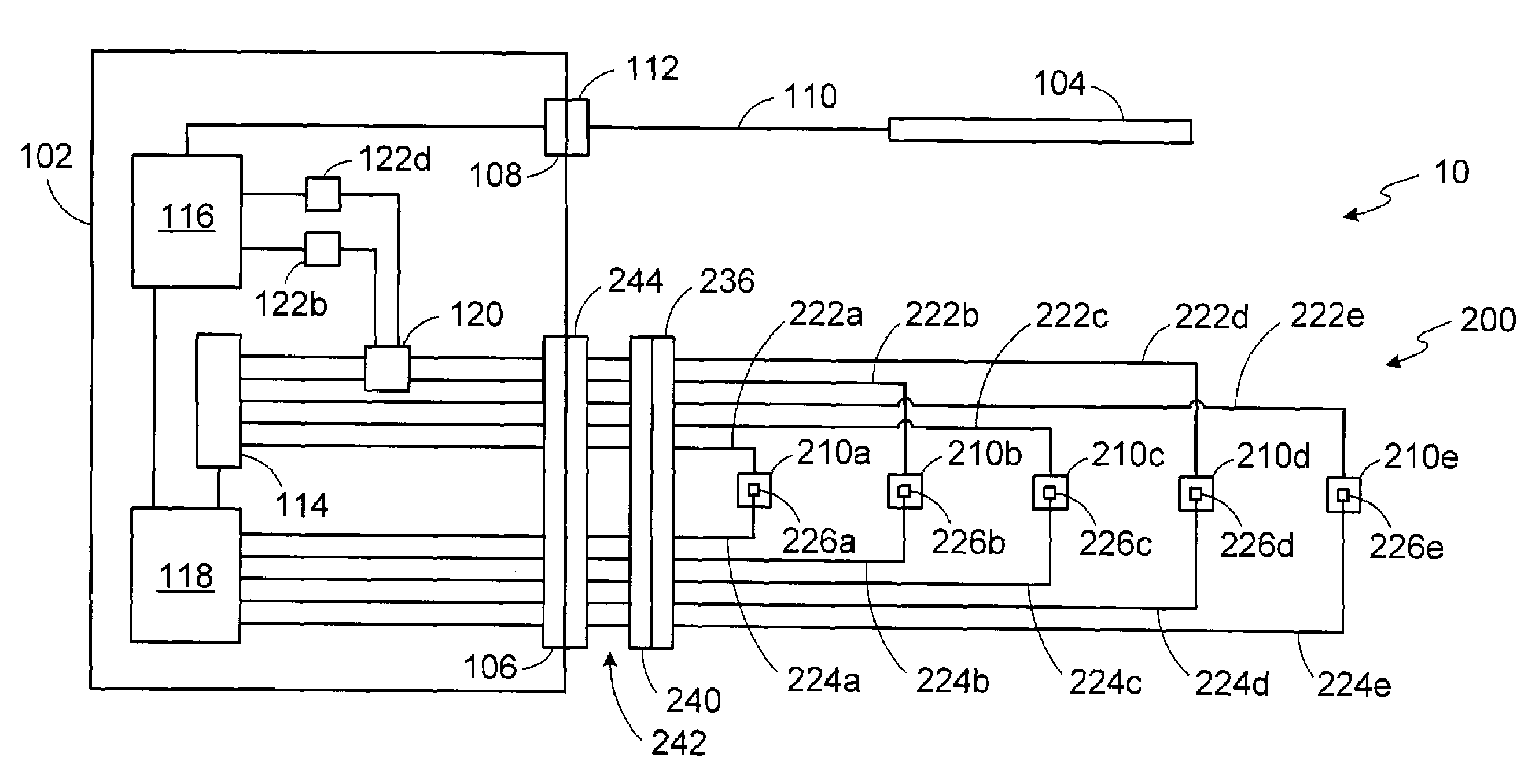
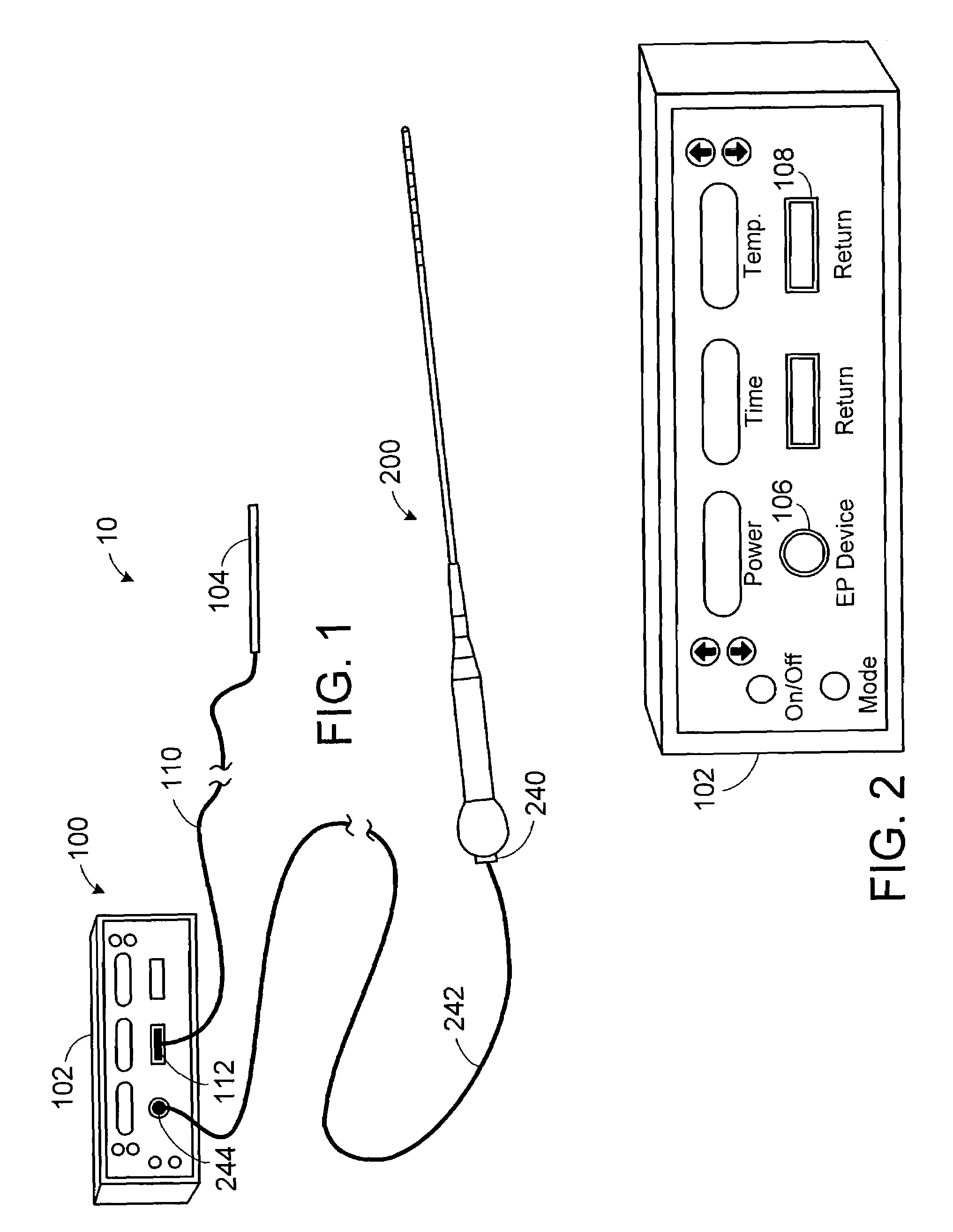
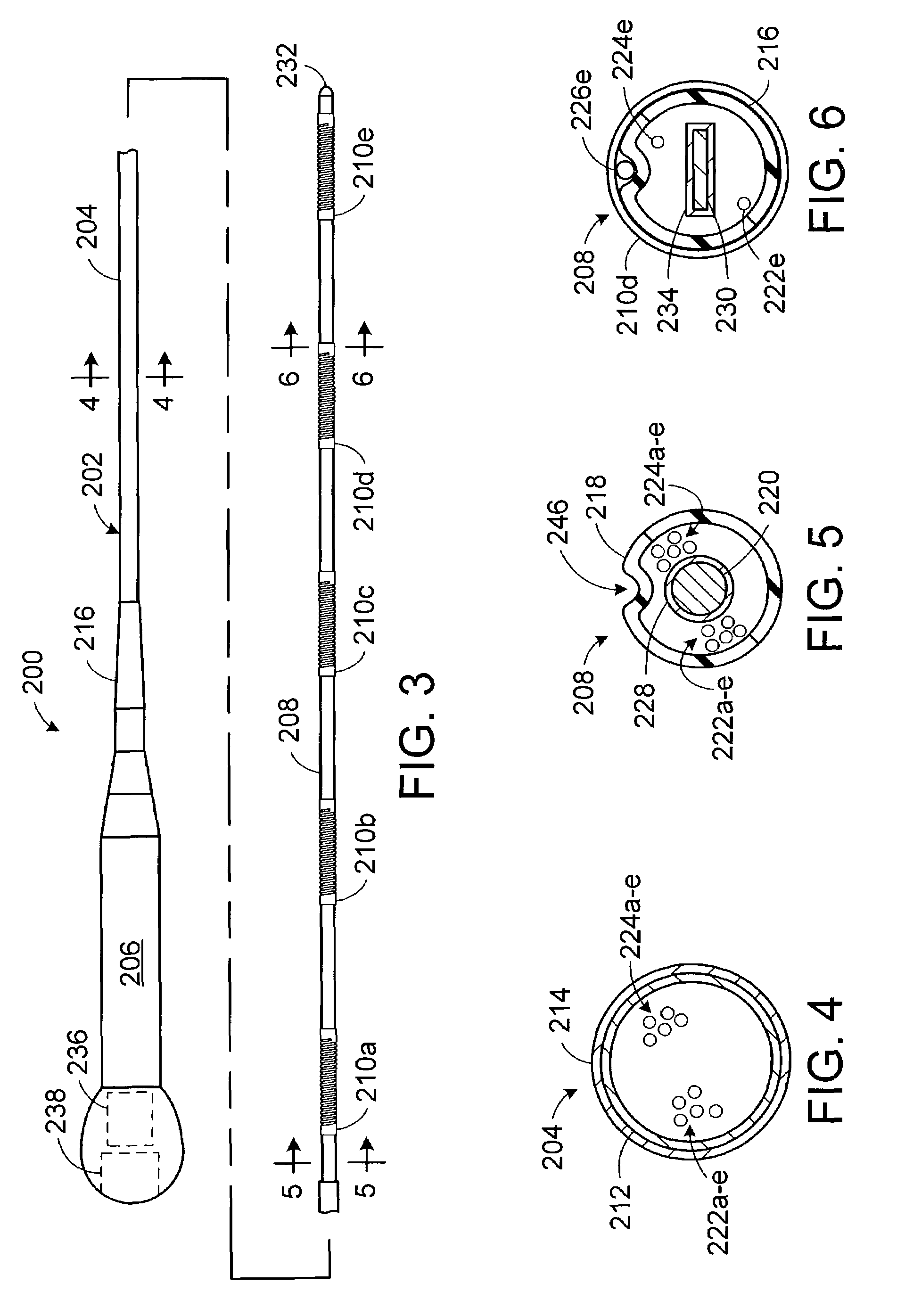
[0033]Electrophysiology systems in accordance with the present inventions include a device that carries a plurality of electrodes and a control system that supplies and controls power to the electrodes in a combined bipolar / unipolar mode. Although not limited to any particular type of device, electrophysiology systems in accordance with the present ...


PUM


Abstract

A power supply and control apparatus operable in a bipolar mode, a unipolar mode, and a combined bipolar/unipolar mode.

Description

BACKGROUND OF THE INVENTIONS[0001]1. Field of Inventions[0002]The present inventions relate generally to electrophysiology systems.[0003]2. Description of the Related Art[0004]There are many instances where therapeutic elements must be inserted into the body. One instance involves the formation of therapeutic lesions to the treat cardiac conditions such as atrial fibrillation, atrial flutter and arrhythmia. Therapeutic lesions may also be used to treat conditions in other regions of the body including, but not limited to, the prostate, liver, brain, gall bladder, uterus and other solid organs. Typically, the lesions are formed by ablating tissue with one or more electrodes. Electromagnetic radio frequency (“RF”) energy applied by the electrode heats, and eventually kills (i.e. “ablates”), the tissue to form a lesion. During the ablation of soft tissue (i.e. tissue other than blood, bone and connective tissue), tissue coagulation occurs and it is the coagulation that kills the tissue...

Claims


Application Information

Patent Timeline
IPC IPC(8): A61B18/12A61B18/14
CPCA61B18/1482A61B2018/1253A61B2018/126A61B2018/1437A61B2018/1467A61B2018/00589
Inventor SWANSON, DAVID K.
Owner BOSTON SCI SCIMED INC
Why Eureka
Try Eureka