Unlock instant, AI-driven research and patent intelligence for your innovation.

Communication system, transmission terminal and receiving terminal therefor

a technology of communication system and receiving terminal, which is applied in the field of communication system, transmitting terminal and receiving terminal therefor, and can solve the problems of deterioration of the operating condition of packet not affected by deterioration, and higher bit error rate of communication in the radio environment than that in the wire environmen

Inactive Publication Date: 2008-04-15
MITSUBISHI ELECTRIC CORP
View PDF7 Cites 5 Cited by
  • Summary
  • Abstract
  • Description
  • Claims
  • Application Information

AI Technical Summary

Benefits of technology

The present invention provides a communication system that can predict the available bandwidth on a radio path based on the jitter moving-average of each packet, and use this information to deliver packets appropriately. The system takes into account both positive and negative-valued jitter, and can make accurate predictions even under poor conditions of communication. The system can control the amount of packets sent and the interval at which packets are sent, and can also designate a packet error correcting scheme based on the available bandwidth. The system can be used in a communication system in which the receiving terminal is connected to a radio path or a wire path, and can also be used in a communication system in which the transmitting and receiving terminals are both connected to a radio path or a mobile terminal is provided to relay packets. The technical effects of the invention include improved packet delivery and better utilization of available bandwidth.

Problems solved by technology

On the other hand, the deterioration of the operating condition for a packet communication in the radio environment is affected not only by the packet congestion but also by aggravation of the communication circumstance due to a change in the connecting condition of the radio path.
Generally, the bit error rate of the communication in the radio environment is higher than that in the wire environment, and in the packet communication a packet containing a bit error is often regarded as invalid (i.e., a packet loss) in its entirety.
With the presence of the error correcting mechanism, however, it appears from the user side that the actual packet loss probability is not so high as the bit error rate.
But, when the delay time by processing in the error correcting mechanism increases, it is observed as if a decrease in the throughput or in the available bandwidth is caused.
That is, the upper limit of the overall bandwidth available on the path also varies.
If the packet delivery is continued in spite of such variations, the situation will also arise where the packet transfer in excess of the available bandwidth continues, which causes a further increase in the delay or packet loss.
This leads to quality deterioration of continuous media information or the like in particular which needs to be delivered on a real-time basis.
In the radio environment the communicating conditions become deteriorated typically when a mobile terminal makes handover.
Since the conventional communication system has such a configuration as described above, if the communicating conditions are badly deteriorated as in the case of handover, it is possible to cope with such a situation in the postprocessing manner, but since the bandwidth available on the radio path is undetectable, it is impossible to perform appropriate packet delivery control in accordance with the communication environment.

Method used


Image

  • Communication system, transmission terminal and receiving terminal therefor
  • Communication system, transmission terminal and receiving terminal therefor
  • Communication system, transmission terminal and receiving terminal therefor

Examples


first embodiment

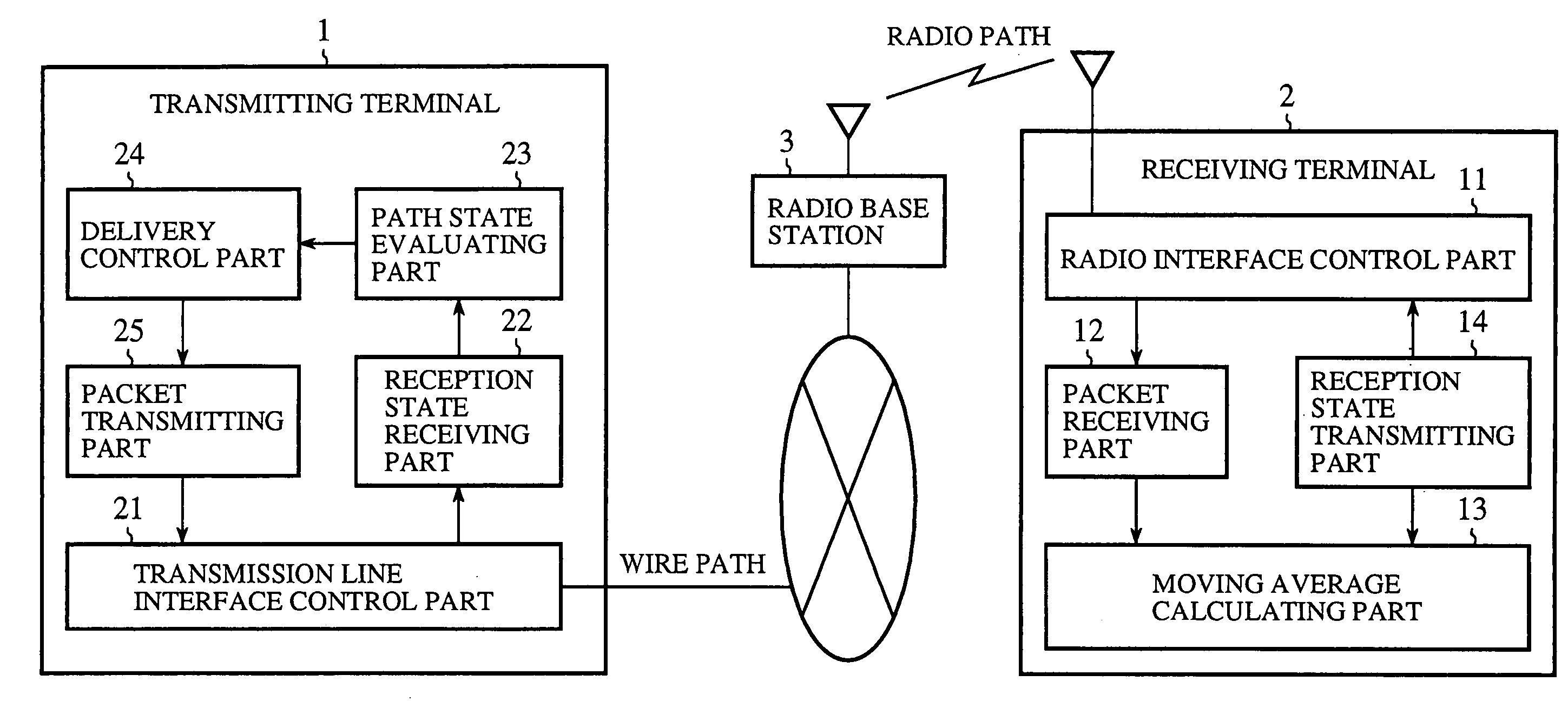
[0047]FIG. 1 is a block diagram illustrating a communication system according to a first embodiment of the present invention. In FIG. 1, reference numeral 1 denotes a transmitting terminal connected to a wire path to send packets, 2 denotes a receiving terminal connected via a radio path to a radio base station 3 to receive packets from the transmitting terminal 1, and 3 the radio base station.

[0048]Reference numeral 11 denotes a radio interface control part; 12 denotes a packet receiving part for receiving packets sent from the transmitting terminal 1; 13 denotes a moving average calculating part for calculating a moving average of jitter from the time of transmission of each packet and the time of reception of the packet received by the packet receiving part 12; and 14 denotes a reception state transmitting part which sends the moving average of jitter calculated by the moving average calculating part 13, as a report indicating the state of reception, to the transmitting terminal ...

second embodiment

[0074]While the first embodiment has been described to predict the available bandwidth on the radio path without specifying any particular radio communication scheme, it is also considered preferable to change the available bandwidth according to the radio communication scheme used.

[0075]Then, a second embodiment will be described to predict the available bandwidth taking into account the radio communication scheme used.

[0076]In the second embodiment the transmitting terminal 1 calculates a difference between a jitter moving average calculated taking into account positive-valued jitter alone and a jitter moving average calculated taking into account not only the positive- but also negative-valued jitter, and updates the previous predicted value in accordance with the ratio of the difference to a predetermined threshold value.

[0077]More specifically, in the first place, the path state evaluating part 23 of the transmitting terminal 1 calculates fluctuations Δ in the available bandwid...

third embodiment

[0079]In the first and second embodiments described above, the delivery control part 24 of the transmitting terminal 1 controls the amount and send interval of the packets to be sent from the packet transmitting part 25 based on the available bandwidth predicted by the path state evaluating part 23, but provision may also be made for the transmitting terminal 1 to indicate a packet error correcting scheme to the receiving terminal 2 in accordance with the available bandwidth.

[0080]That is, when the communication condition in the radio environment becomes worse, the error correcting mechanism in the data link layer or the lower layer performs the error correcting processing, resulting in an increase in the number of packets waiting for delivery in a base station or halfway (at a router or the like) on the communication path; too large a number of packets waiting for delivery causes packet losses in the base station and halfway on the communication path. This calls for further error c...


PUM


Abstract

A communication system, including: a transmitting terminal configured to transmit a plurality of data packets; and a receiving terminal configured to receive the plurality of data packets, wherein the receiving terminal is configured to calculate a first jitter moving average from a transmitting time and a receiving time of each packet received by the receiving terminal based on positive-valued jitter and negative-valued jitter, to calculate a second jitter moving average from the transmitting time and receiving time of each packet received by the receiving terminal based only on positive-valued jitter, and to send the first and the second jitter moving averages to the transmitting terminal, and the transmitting terminal is configured to predict an available bandwidth on a communication path between the transmitting terminal and the receiving terminal based on a comparison of the first and second jitter moving averages.

Description

TECHNICAL FIELD[0001]The present invention relates to a communication system, transmitting terminal and a receiving terminal which implement an efficient packet delivery in a communication environment containing a radio path.BACKGROUND ART[0002]The deterioration of the operating condition for a packet communication in a wire environment is attributable to the congestion resulting from concentration of many packets in a narrow-bandwidth path which forms a communication bottleneck; usually, reduction in the bandwidth is not caused by worsening of the connecting condition of the path itself. That is, the upper limit of the overall bandwidth available on the path is fixed. Accordingly, the quality of communication between transmitting and receiving terminals could be improved by detecting the congestion on the path and performing delivery control in accordance with the congestion.[0003]On the other hand, the deterioration of the operating condition for a packet communication in the radi...

Claims


Application Information

Patent Timeline
Patent Type & Authority Patents(United States)
IPC IPC(8): H04L1/00H04J3/06H04J3/07H04J3/24H04L1/20H04L12/28H04L47/22
CPCH04L1/205H04L1/0009
Inventor FUKUDA, KAZUMA
Owner MITSUBISHI ELECTRIC CORP