Sensor assembly

a sensor and fingertip technology, applied in the field of fingertip sensors, can solve the problems of fingertip sensors easily falling off, springs are intentionally relatively weak, and pressure exerted by them, and achieve the effect of improving mechanical isolation

Active Publication Date: 2008-04-15
NONIN MEDICAL
View PDF25 Cites 36 Cited by
  • Summary
  • Abstract
  • Description
  • Claims
  • Application Information

AI Technical Summary

Benefits of technology

[0009]The present invention is directed to a sensor assembly which provides improved mechanical isolation between the sensor holder region and other regions of the sensor assembly. In one embodiment, the sensor assembly includes a collar, a fenestrated region, a sensor holder, and a sensor. The collar, the fenestrated region, and the sensor holder are preferably made of a flexible material, such as a polymer. The sensor can include any known sensors used for monitoring of physiological parameters.
[0011]In one embodiment, the fenestrated region includes a plurality of bridges separated by windows. The fenestrated region may additionally be of a reduced thickness compared to other portions of the sensor assembly. In another embodiment of the invention, the fenestrated region can include one relatively large opening in the sensor assembly. The fenestrated region may respond to external forces transferred through the collar by substantial deformation, including stretching, twisting, buckling and bending. As a result, the fenestrated region contributes to mechanical isolation of the sensor holder from the collar. Consequently, when a force is applied to the collar, the relatively thin fenestrated region is able to stretch or distort without disrupting the sensor holder. The fenestrated region which can include one or more fenestrations or openings into the interior of the sensor assembly, promotes an increase in user comfortability and digit ventilation. The fenestrated region is optional and embodiments of the present invention may be device of one or more fenestrations.
[0012]In one embodiment, the sensor holder provides seats wherein portions of the sensor element is received. The seats are positioned such that the sensor element is optimally located with respect to the patient. A finger stop and guide may be provided within an interior of the finger assembly in order to facilitate the positioning of the finger relative to the sensor element.
[0013]In one embodiment, an elongated pleat extends across each lateral side of the sensor assembly. The pleats enable the sensor assembly to expand and accommodate a variety of finger sizes.

Problems solved by technology

One such cause of local vasococompression is the pressure exerted by the sensor on the finger.
Since excess pressure on the finger can dampen or eliminate the pulsation in the blood supply to the finger, these springs are intentionally relatively weak.
The result of this compromise is that the spring-held sensors readily fall off the finger.
Many known non-disposable sensors are relatively bulky.
This results in a susceptibility to relative motion between the sensor and the finger as the finger is moved.
Motion artifacts caused by displacement of the lead wire are especially problematic for oximetric sensors.

Method used


Image

  • Sensor assembly
  • Sensor assembly
  • Sensor assembly

Examples


Embodiment Construction

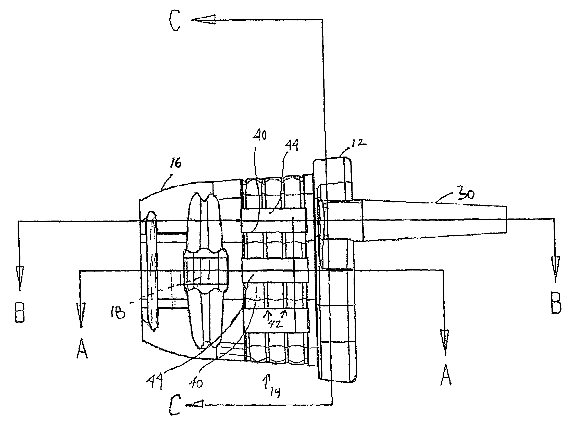
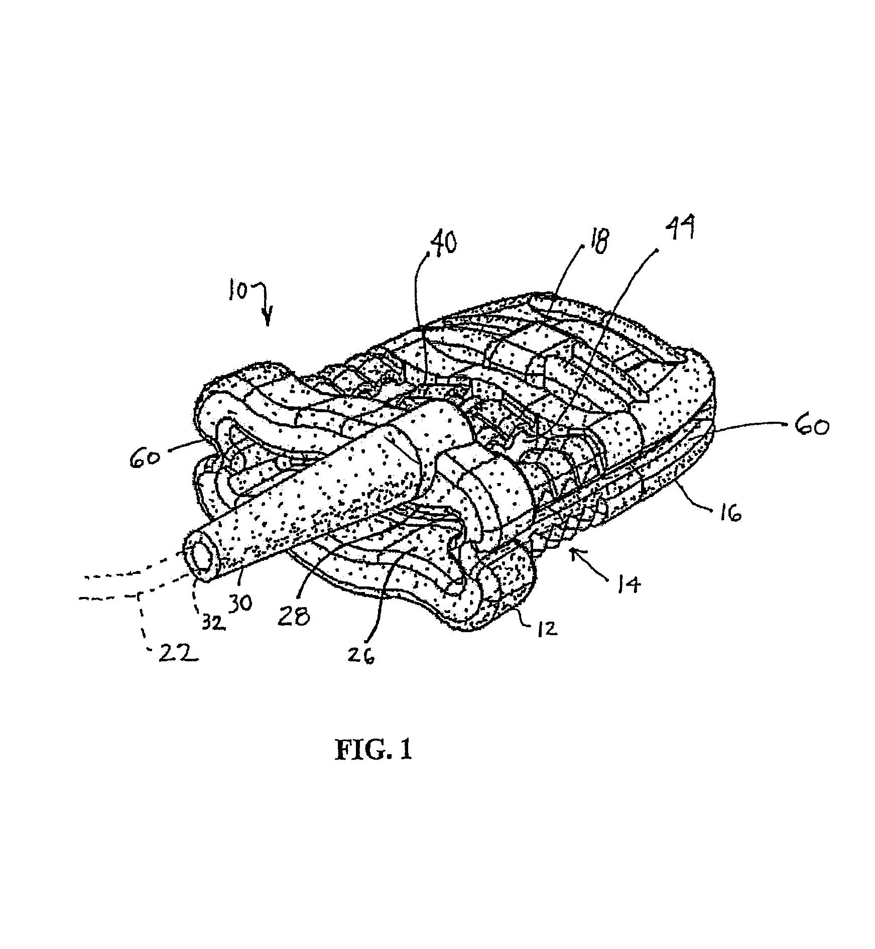
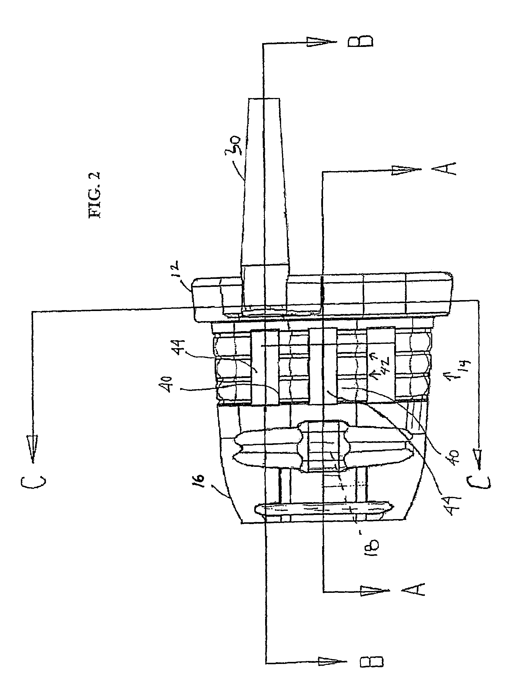
[0027]In one embodiment of the present invention, as shown in FIGS. 1-6, a finger sensor assembly 10 is provided which mechanically isolates the sensor elements relative to other portions of the sensor assembly 10 in order to minimize inadvertent displacement of the sensor elements caused by external forces. For the purposes of explanation only, the present invention is disclosed utilizing an embodiment that is configured for the measurement of oxygen saturation through known oximetric transmittance techniques. As one skilled in the art can readily appreciate, the present invention is easily adaptable to accommodate a number of different physiological monitoring applications and configurations, including but not limited to, other optical sensors, reflective sensor, etc.

[0028]FIG. 1 illustrates an embodiment of the assembly 10 adapted as an electro-optical sensor for a fingertip. In the illustrated embodiments, sensor assembly 10 is utilized within a system including a monitoring uni...


PUM


Abstract

A flexible finger sensor having a finger entrance, a sensor holder at a distal end of the assembly, and a fenestrated region disposed between the finger entrance and the sensor holder. A displacement resistant finger sensor and method of use for reducing motion-related artifacts by mechanical isolation from external forces by providing a resilient sensor body having a digit entrance, a sensor holder, and a fenestrated region between the digit entrance and the sensor holder. The sensor holder maintains sensing elements relative to a user's finger, with said sensing elements being in communication with a monitoring device via a lead wire. The lead wire may extend at a lateral edge of the sensor body. A force to the lead wire may be applied so as to distort the fenestrated region without substantially disturbing the sensing elements relative to the finger surface.

Description

FIELD OF THE INVENTION[0001]The present invention relates generally to physiological sensors. More specifically, the present invention relates to a fingertip sensor adapted to improve sensor stability in order to minimize the occurrence of motion-induced artifacts within a physiologic signal.BACKGROUND OF THE INVENTION[0002]Non-invasive physiological monitoring is a common means for testing, detecting, and treating a physiological condition. Typically, non-invasive monitoring techniques such as pulse oximetry, electrocardiography (ECG), electroencephalography (EEG), and ultrasonic imaging, to name a few, require that a sensor be placed in direct contact with a patient undergoing the procedure.[0003]Pulse oximetry involves the non-invasive monitoring of oxygen saturation level in blood-profused tissue indicative of certain vascular conditions. In practice, light is passed through a portion of a patient's body which contains arterial blood flow. An optical sensor is used to detect lig...

Claims


Application Information

Patent Timeline
Patent Type & Authority Patents(United States)
IPC IPC(8): A61B5/00
CPCA61B5/14552A61B5/6826A61B5/6838
Inventor MASER, DOUGLAS R.JOHNSON, TIMOTHY L.ISAACSON, PHILIP O.
Owner NONIN MEDICAL
Why Eureka
Try Eureka