
Apparatus for hand propulsion and steering of a scooter, tricycle or bicycle

a technology for scooters and tricycles, which is applied in the direction of bicycles, vehicle components, rider propulsion, etc., can solve the problems of preventing their commercial success, lack of simplicity, and prohibitive cost of these items, so as to achieve sufficient top speed and reduce power loss

Inactive Publication Date: 2008-04-22
TUCKER JOE W
View PDF12 Cites 13 Cited by
  • Summary
  • Abstract
  • Description
  • Claims
  • Application Information

AI Technical Summary

Benefits of technology

[0013]This simplicity results in low cost, light weight, easy maintenance, and efficient propulsion. The operator both propels and steers the vehicle with a single set of handlebars which pivot, for steering, about a point close to the axis of the steering column. Steering is comfortable, positive, effective, and very similar to the steering of a conventional bicycle.
[0014]Propelling force is delivered during the downward movement of the handlebars in an up-and-down stroke cycle, in which the operator uses his weight as the driving force. Maintaining his balance is not a problem, and the propelling and steering functions work smoothly together.
[0015]The use of the operator's weight in the downward movement of the handlebars permits a forceful transfer of energy, and the power stroke is long enough that the vehicle is moved a considerable distance with each stroke. This prevents the excessive loss of energy caused by the large number of reversals of the reciprocating components in most designs of the prior art.
[0017]At first glance it would seem that power is applied only one-half the time, but this is not the case. The upward, return stroke of the handlebars is uninhibited and very fast, while the downward power stroke is much slower, resulting in power transfer during about seventy-five percent of the time. The fact that the present design uses only one one-way clutch, and can use all lightweight cable for the drive member, further reduces the power losses from reciprocation of components.
[0018]A distinct advantage is offered by the present invention in that it does not require one or multiple rewind springs, as do a large majority of the designs of the prior art. These springs are usually difficult to design properly to fulfill all requirements, and most often require additional reciprocating components.
[0019]The present design allows a large and forceful movement of the handlebars with each downward power stroke. This provides a sufficient top speed without the power losses associated with a short stroke and more frequent reversals of the reciprocating components of a system.

Problems solved by technology

Hand powered vehicles are well represented in the prior art; however, a large percentage of the designs have major flaws which might well prevent their commercial success.
Among the most prevalent of these flaws is the lack of simplicity, which make the cost of these items, most of which might be classified as children's toys, prohibitive.
The extra components also require extra energy to operator, especially the reciprocating components, and they add to the weight and upkeep.
This, in turn, causes an inefficient operation, as the power losses in reversing the reciprocating components increase as the square of the velocity.
For those designs which utilize a spring to rewind one or more one-way clutches on the reverse stroke, the spring is almost always a problem.
Providing the necessary distance capacity and strength for the spring is always a challenge, and in several of the designs in the prior art the spring design appears to be inadequate.
The steering mechanism is questionable in U.S. Pat. No. 6,942,234, to Chait, which involves tilting the propulsion levers, and U.S. Pat. No. 5,690,346, to Keskitalo, and U.S. Pat. No. 5,272,928, to Young, both utilize a very small pulley on the steering column which is activated by cables, and very likely does not operate properly.
It is doubtful that this will be effective, as the operator is not able to spread his feet front-to-back on the platform in order to exert enough horizontal force on the handlebars.
U.S. Pat. No. 2,123,390, to Welch, and U.S. Pat. No. 1,598,855, to Dunlop, operate in a manner similar to the Lindsey design, and would probably present the same problem.

Method used


Image

  • Apparatus for hand propulsion and steering of a scooter, tricycle or bicycle
  • Apparatus for hand propulsion and steering of a scooter, tricycle or bicycle
  • Apparatus for hand propulsion and steering of a scooter, tricycle or bicycle

Examples


Embodiment Construction

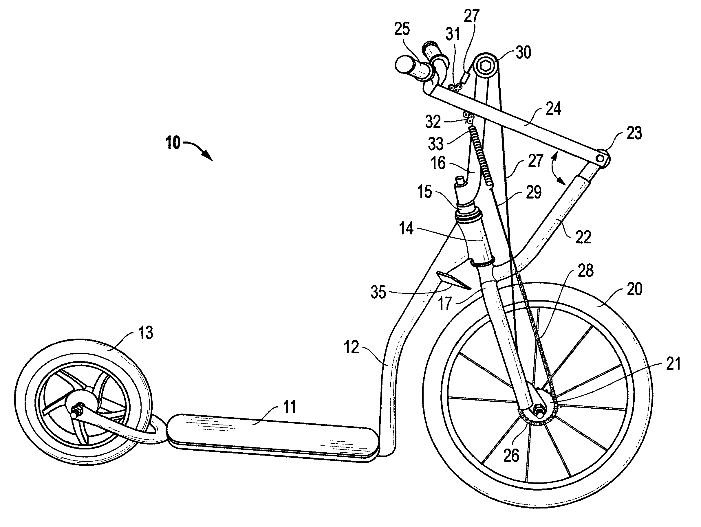
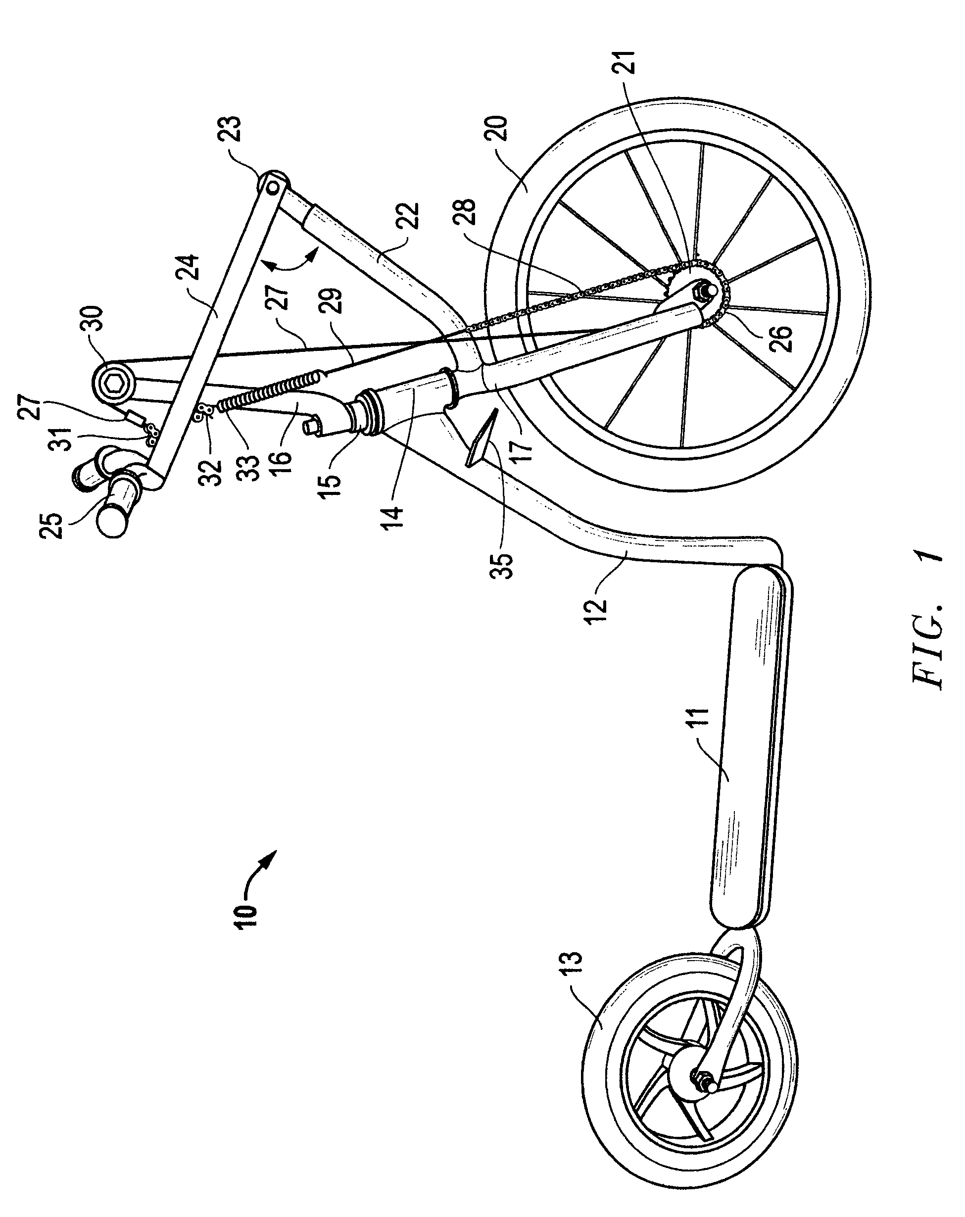
[0026]FIG. 1 is a side view of the preferred embodiment of the present invention in a scooter referred to as scooter 10. Floorboard 11 of scooter 10 supports the operator and is attached to framework 12, which rotatably supports rear wheel 13 at its rear portion and is joined to steering column journal means 14 at its upper forward portion. Steering column 15 is rotatably supported by steering column journal means 14, and supports idler pulley mast 16 at its upper end, and fork 17 at its lower end.

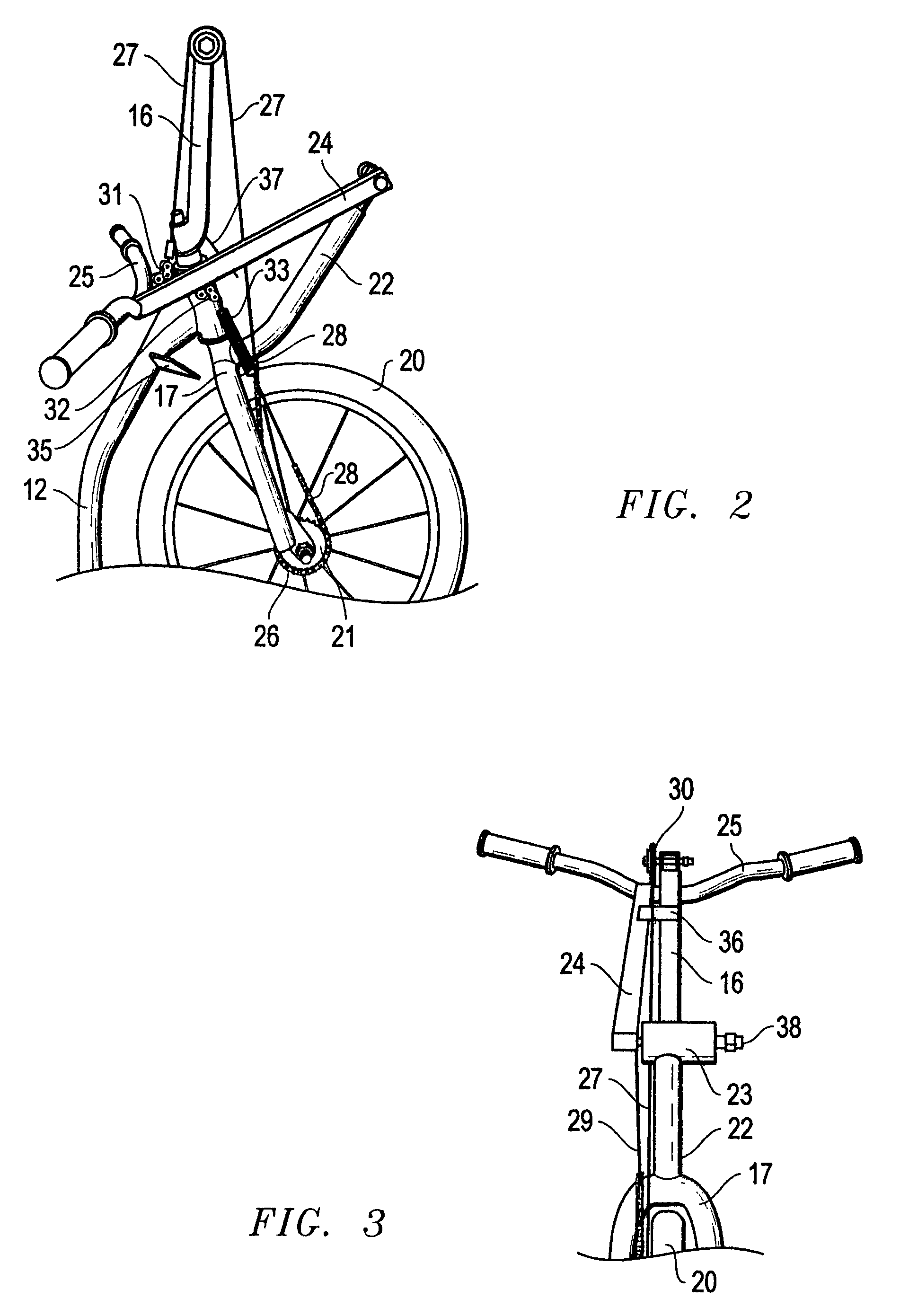
[0027]Fork 17 rotatably supports front drive wheel 20, which has one-way clutch 21 attached to its hub. Drive / steering level support mast 22 is joined to the forward side of fork 17 close to the point at which it joins steering column 15, and extends upward and forward to a point at which it supports drive / steering lever journal means 23 (refer to FIGS. 3 and 4 also).

[0028]Drive / steering level 24 and handlebars 25 are supported for up-and-down movement by drive / steering level journal means...


PUM


Abstract

An apparatus is disclosed by means of which an operator both propels and steers a scooter, tricycle, or bicycle with a single set of handlebars. Power is applied by pumping the handlebars up and down, and steering is positive, and very similar to that of a conventional bicycle or tricycle. Drive means includes a single one-way clutch and a reciprocating endless chain or cable member which does not require a rewind spring. The total mechanism is very simple, the reciprocating components are few and light weight, and a long stroke yields a functional efficiency and top speed.

Description

FIELD OF THE INVENTION[0001]This invention is one in which the operator's hands furnish power to propel a wheeled vehicle and in which steering for the vehicle is provided, and more particularly, in which the hands operate a single set of handlebars which transfers motive power and also handles the steering.[0002]Power is transferred by pumping the handlebars up and down, and steering is accomplished by twisting the handlebars around an approximately vertical axis, and is very similar to the steering of a conventional bicycle.[0003]Power transfer utilizes a one-way clutch, which is common in the comparable art, along with an endless loop of a drive member which can be a chain, cable, strap, or combination. The drive member engages the one-way clutch and is reciprocated by the up-and-down movement of the handlebars. The invention will be described in this specification with emphasis given to its scooter application.BACKGROUND OF THE INVENTION[0004]Hand powered vehicles are well repre...

Claims


Application Information

Patent Timeline
IPC IPC(8): B62M1/14
CPCB62K3/002B62M1/16
Inventor TUCKER, JOE W.
Owner TUCKER JOE W
Learn More