
Rail road car with reduced slack

a rail road car and slack technology, applied in the field of auto rack rail road cars, can solve the problems of frequent damage claims, significant longitudinal acceleration, and need for slack, and achieve the effects of reducing the accumulation of slack, reducing the relative longitudinal motion, and reducing the associated velocity differential and acceleration

Inactive Publication Date: 2008-04-22
NATIONAL STEEL CAR
View PDF139 Cites 13 Cited by
  • Summary
  • Abstract
  • Description
  • Claims
  • Application Information

AI Technical Summary

Benefits of technology

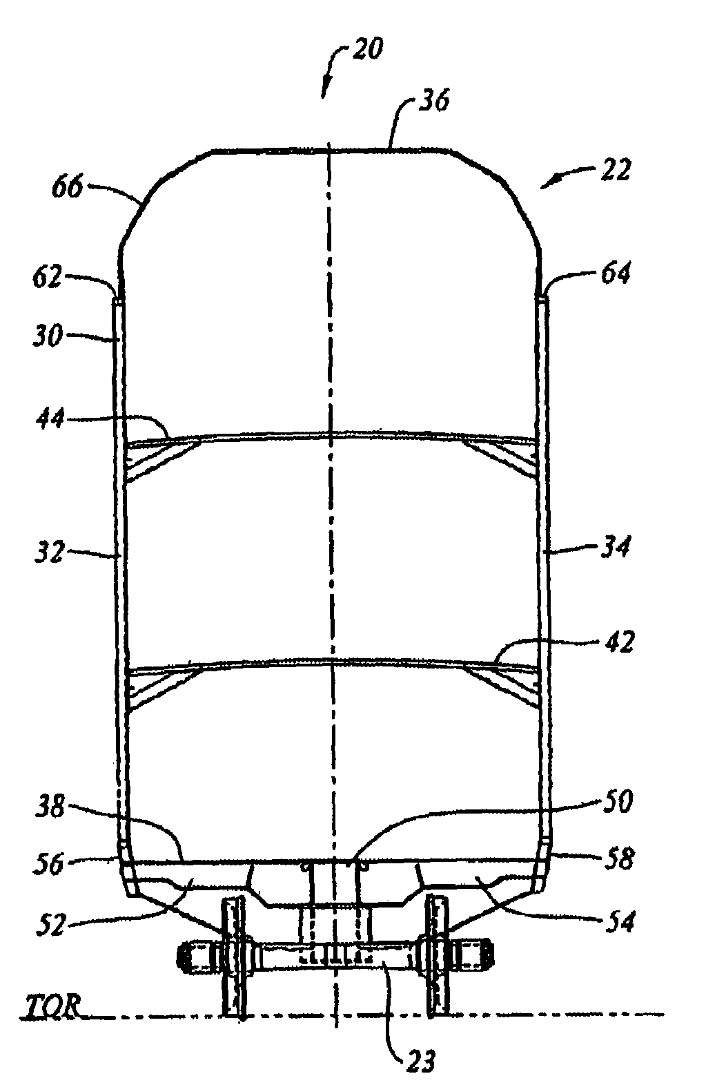
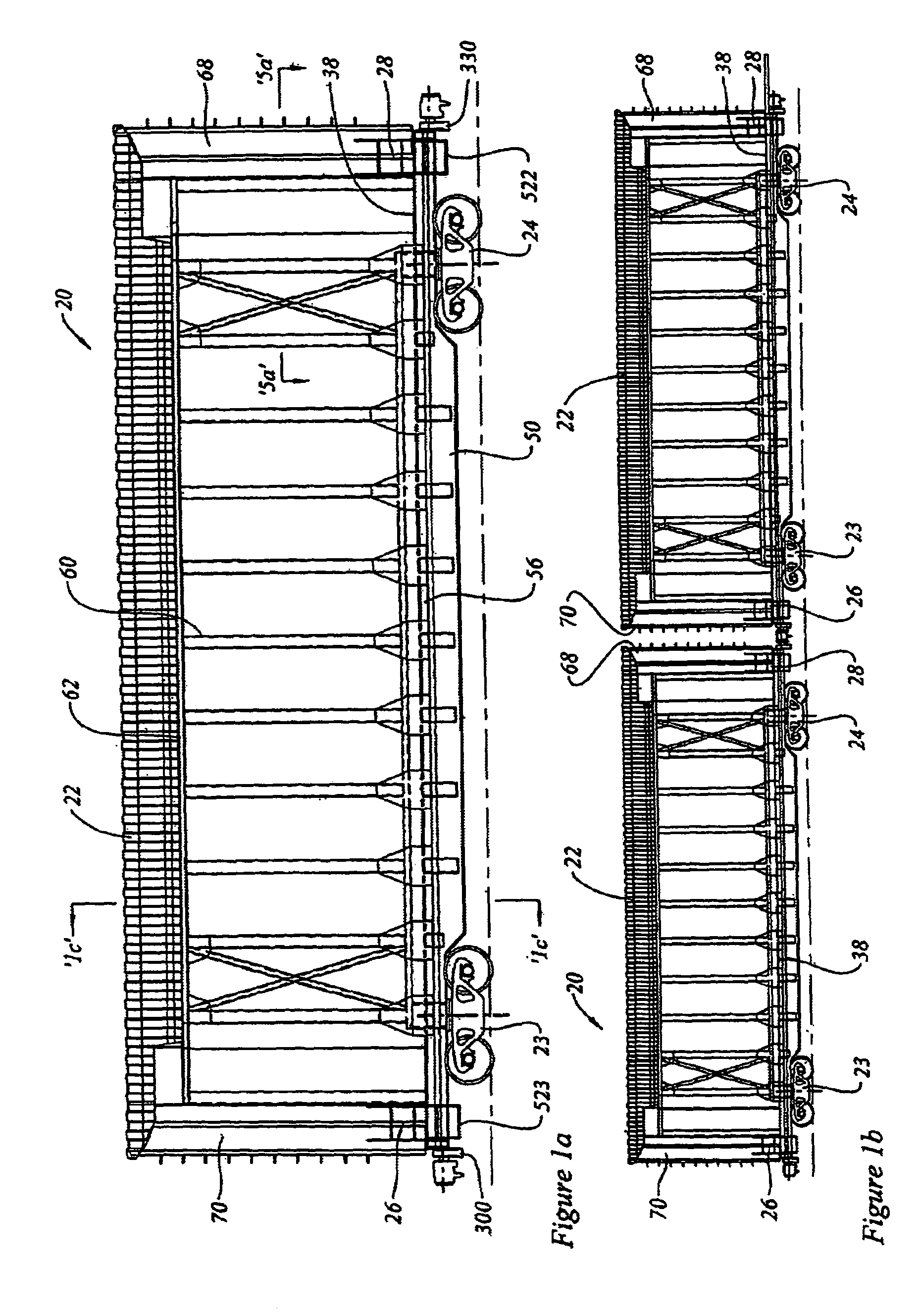
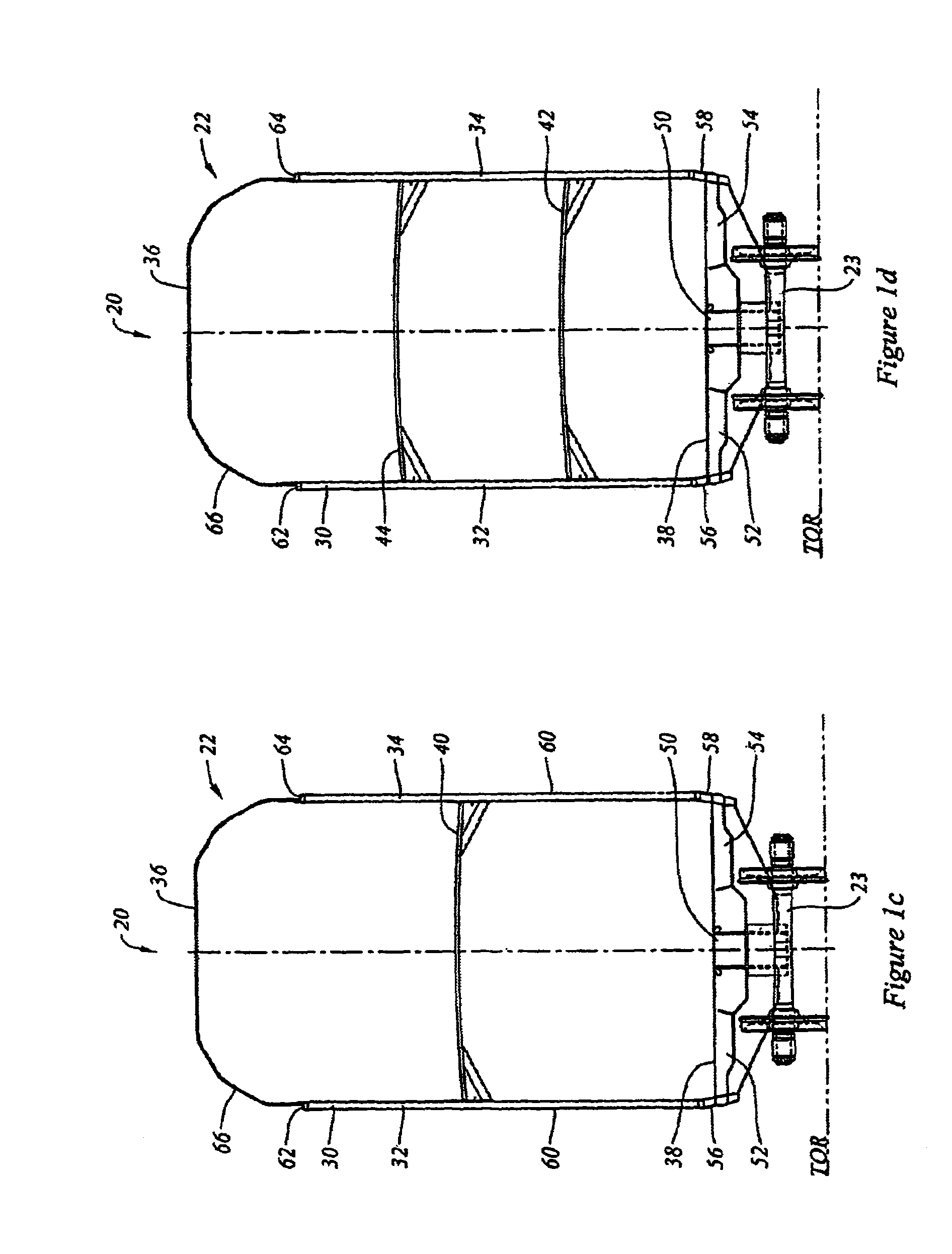
The invention is an auto rack rail road car that can carry automobiles and has a unique design for safely and efficiently loading and unloading them. The car has a rail body that can roll and is supported at each end by a draft gear and releasable coupler. The coupler has low deflection under a buff load and is designed to have less than 2 inches of deflection at a load of 700,000 lbs. The car also has a deck access apparatus for safely and easily accessing the decks of the car. The invention also includes a combination of two auto rack rail road cars that can be joined together to form a coupling for carrying wheeled vehicles.

Problems solved by technology

A long standing concern has been the frequency of damage claims arising from high accelerations imposed on the lading during train operation.
Many of these damage claims are related to slack action in the train.
This slack run-in and run-out can result in significant longitudinal accelerations.
Historically, the need for slack was related, at least in part, to the difficulty of using a steam locomotive to “lift” (that is, move from a standing start) a long string of cars with journal bearings, particularly in cold weather.
For this type of operation the coupling speeds can be excessive, resulting in similarly excessive car body accelerations.
For many types of rail road car, humping is now forbidden due to the probability of damaging the lading.
This often less than gentle habit tends to lead to rather high impact loads during coupling at impacts in the 5 m.p.h.
Forces can be particularly severe when there is an impact between a low density lading rail road car, such as an auto rack car, and a high density lading car (or string of cars) such as coal or grain cars.
While this may be acceptable for coal or grain, it is undesirably severe for more sensitive lading, such as automobiles or auto parts, paper, and other consumer goods such as household appliances.
However, by eliminating, or reducing, the accumulation of slack, the use of short travel buff gear may tend to reduce the relative longitudinal motion between adjacent rail road cars, and may tend to reduce the associated velocity differentials and accelerations between cars.
AAR Type H couplers are expensive, and are used for passenger cars, as were the alternate standard Type CS controlled slack couplers.
647 “Although it was anticipated at one time that the F type coupler might replace the E as the standard freight car coupler, the additional cost of the coupler and its components, and of the car structure required to accommodate it, have led to its being used primarily for special applications”.
Elimination of slack between coupler heads, plus Mini-Buff Gear's high pre-load and limited travel, provide ultralow slack coupling for multiple-unit well cars and drawbar connected groups of unit train coal cars.” Notably, unlike vehicle carrying rail cars, coal is unlikely to be damaged by the use of short travel draft gear.

Method used


Image

  • Rail road car with reduced slack
  • Rail road car with reduced slack
  • Rail road car with reduced slack

Examples


Embodiment Construction

[0057]The description that follows, and the embodiments described therein, are provided by way of illustration of an example, or examples, of particular embodiments of the principles of the present invention. These examples are provided for the purposes of explanation, and not of limitation, of those principles and of the invention. In the description, like parts are marked throughout the specification and the drawings with the same respective reference numerals. The drawings are not necessarily to scale and in some instances proportions may have been exaggerated in order more clearly to depict certain features of the invention.

[0058]In terms of general orientation and directional nomenclature, for each of the rail road cars described herein, the longitudinal direction is defined as being coincident with the rolling direction of the car, or car unit, when located on tangent (that is, straight) track. In the case of a car having a center sill, whether a through center sill or stub si...


PUM


Abstract

A rail road car has a rail car body which includes a housing structure. The housing structure has a pair of sidewalls, a roof and at least one deck mounted to the sidewalls. An enclosed lading space is defined by the housing structure and there is at least one door for controlling access to the enclosed space. The rail road car is provided with short travel buff gear and a reduced slack, or slackless, coupler.

Description

RELATED APPLICATIONS[0001]This is a continuation application of U.S. patent application Ser. No. 10 / 366,094 filed Feb. 12, 2003, now U.S. Pat. No. 6,821,065, which is a continuation of U.S. patent application Ser. No. 09 / 658,856, filed Sep. 11, 2000, now U.S. Pat. No. 6,551,039, the specification of which is hereby incorporated by reference.FIELD OF THE INVENTION[0002]This invention relates to the field of auto rack rail road cars for carrying motor vehicles.BACKGROUND OF THE INVENTION[0003]Auto rack rail road cars are used to transport automobiles. Most often, although not always, they are used to transport finished automobiles from a factory to a distribution center. A long standing concern has been the frequency of damage claims arising from high accelerations imposed on the lading during train operation. Many of these damage claims are related to slack action in the train. In this context, slack action includes (a) the free slack in the couplers; and (b) the travel of the draft ...

Claims


Application Information

Patent Timeline
Patent Type & Authority Patents(United States)
IPC IPC(8): B60P7/00B61D3/02B61D3/18
CPCB61D3/02B61D3/18B61D3/187
Inventor FORBES, JAMES W.
Owner NATIONAL STEEL CAR
Learn More