Linear motor, exposure apparatus using the same, and device manufacturing method

a linear motor and exposure apparatus technology, applied in the field of linear motors, can solve the problems of increasing heat generation, deteriorating positional accuracy of the apparatus, so-called cogging, etc., and achieve the effect of improving heat generation characteristics and shortening the apparent slot pitch

Inactive Publication Date: 2008-04-22
CANON KK
View PDF13 Cites 1 Cited by
  • Summary
  • Abstract
  • Description
  • Claims
  • Application Information

AI Technical Summary

Benefits of technology

[0008]An object of the present invention is to provide a movable magnet-type linear motor, having an iron core, capable of substantially reducing cogging to zero to improve a heat generation characteristic.
[0015]According to the present invention, a pseudo-slot is provided between respective adjacent slots to shorten the apparent slot pitch, i.e., a cogging period, and the magnet and the iron core element are skewed substantially by the cogging period. By doing so, the cogging becomes zero in the movable magnet-type linear motor having the iron core and it is possible to provide a linear motor improved in heat generation characteristic.

Problems solved by technology

As a problem of the linear motor having the iron-core, there is so-called cogging due to an attractive force between the magnet and the iron core.
The cogging is a disturbance which occurs irrespective of the presence or absence of a current and deteriorates a positional accuracy of the apparatus.
Further, an additional current is required for driving, thus increasing heat generation.
Further, the skew causes a lowering in magnetic flux interlinking the coil to lower a generation efficiency of thrust with respect to an input current, thus increasing heat generation.

Method used


Image

  • Linear motor, exposure apparatus using the same, and device manufacturing method
  • Linear motor, exposure apparatus using the same, and device manufacturing method
  • Linear motor, exposure apparatus using the same, and device manufacturing method

Examples


first embodiment

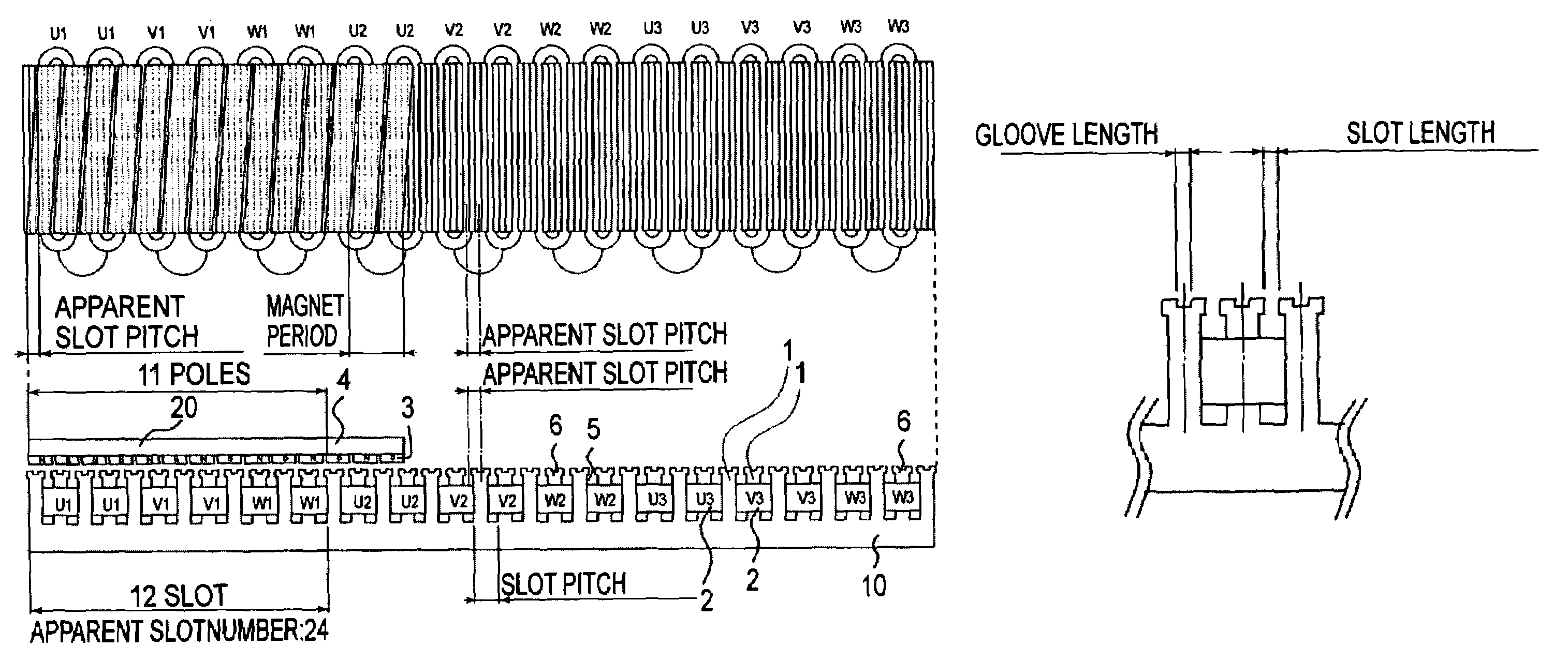
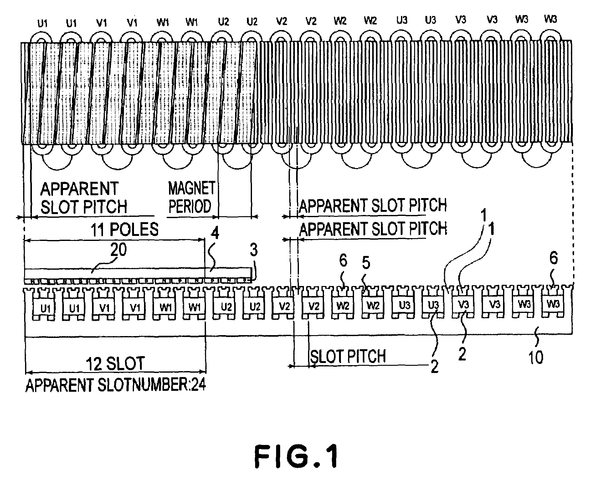
[0044]FIG. 1 shows a structure of a movable magnet-type linear motor according to this embodiment of the present invention.

[0045]In the linear motor shown in FIG. 1, a plurality of iron core elements 1 and disposed on an unshown base in parallel with each other at a certain spacing, and each coil 2 is wound about an associated iron core element 1 to form an armature (iron) core. There armature cores are integrally connected together to form a stator 10 of the linear motor. A magnet array (magnet train) comprising a plurality of magnets 3 arranged in a drive axis direction so as to face an upper surface of the stator 10 via a gap and a back-yoke 4 for circulating magnetic flux of the magnet array are disposed to constitute a linear motor movable part 20. The linear motor movable part is fixed on an unshown stage which is guided by an unshown guide and is driven in the drive axis direction. By using the coil having the iron core, a large thrust can be ensured.

[0046]Further, the movabl...

second embodiments

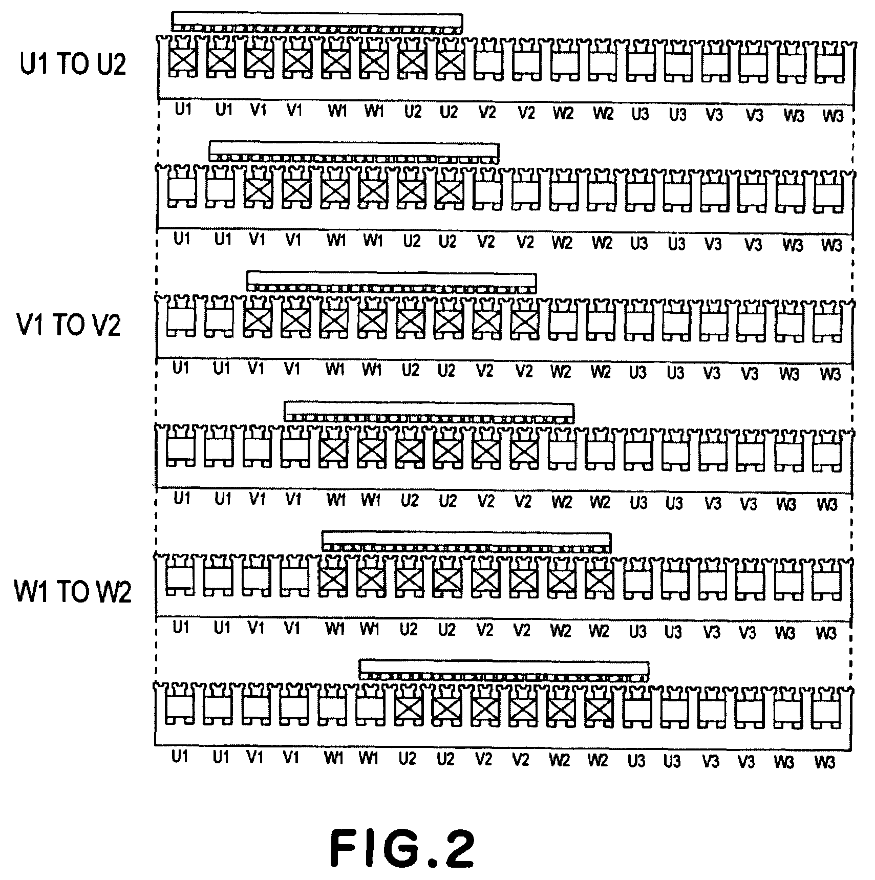
[0079]FIG. 13 shows a structure of a movable magnet-type linear motor according to this embodiment of the present invention.

[0080]The linear motor has the same structure and basic design as those in First Embodiment except that the shape of iron core element and the arrangement of magnet array are changed.

[0081]First of all, the structure of iron core elements of the stator in the linear motor shown in FIGS. 1 and 2 will be described.

[0082]Each of the iron core elements 1 arranged in parallel at a certain spacing is provided with grooves 6 disposed at its end surface facing the magnet array of the movable part 20 so that the grooves 6 are perpendicular to the moving direction of the movable part 20. By doing so, it is possible to reduce a period of cogging as a feature of the linear motor according to the present invention. In this embodiment, two grooves 6 are provided at a central portion of an end surface of one iron core element 1.

[0083]In an actual linear motor, the number of g...


PUM

PropertyMeasurementUnit
electrical angleaaaaaaaaaa

Abstract

In a movable magnet-type linear motor including a stator having a plurality of iron core elements arranged at a certain slot pitch and a movable part having a magnet 3 which is movable in an arrangement direction one or more pseudo-slots are provided between adjacent slots, and the iron core element and the magnet are relatively skewed by an approximately apparent slot pitch including the pseudo-slot.

Description

FIELD OF THE INVENTION AND RELATED ART[0001]The present invention relates to a linear motor, particularly a linear motor for use in a precision drive apparatus such as a machine tool or a semiconductor manufacturing apparatus.[0002]A linear motor has been frequently used in a precision drive apparatus such as a machine tool or a semiconductor manufacturing apparatus. The machine tool or the semiconductor manufacturing apparatus is required to satisfy a drive accuracy, a large thrust for improving productivity, and a light weight mover(movable part).[0003]FIG. 23 shows a conventional linear motor disclosed in Japanese Laid-Open Patent Application (JP-A) No. Hei 11-308850. An armature iron core is disposed on a base and a coil is fixedly wound around the armature core to form a stator of the linear motor. A magnet array comprising a plurality of magnets disposed in a drive axis direction so as to be opposite to an upper surface of the stator via a gap and a connecting member for integ...

Claims


Application Information

Patent Timeline
Patent Type & Authority Patents(United States)
IPC IPC(8): H02K41/00H02K1/00G03F7/20H02K29/03H02K41/03
CPCG03F7/70758H02K41/03Y10T29/49009H02K29/03
Inventor UCHIDA, SHINJI
Owner CANON KK
Why Eureka
Try Eureka