Method for planning or provisioning data transport networks

a data transport network and data technology, applied in the direction of transmission monitoring, frequency-division multiplex, instruments, etc., can solve the problems of large dependence on the complexity of the rfwa function, complex and time-consuming algorithms, and the disclosure of tools that do not provide protection lightpaths

Active Publication Date: 2008-04-22
TELECOM ITALIA SPA
View PDF8 Cites 40 Cited by
  • Summary
  • Abstract
  • Description
  • Claims
  • Application Information

AI Technical Summary

Problems solved by technology

The complexity of the RFWA function greatly depends on the wavelength conversion capability of the switching nodes of the network.
Unfortunately in WDM networks many variables are integer and the exact solution can be obtained only with very complex and time-consuming algorithms (Integer Linear Programming, or ILP, problem).
As recognized by the same authors, the disclosed tool does not provide protection lightpaths for the connection lightpaths found.
As a consequence, a failure occurring in a component of the network (for example a fiber cut or even a whole cable cut) becomes more and more critical, as a failure can result in a huge loss of information.
Clearly, the most critical situation is r

Method used


Image

  • Method for planning or provisioning data transport networks
  • Method for planning or provisioning data transport networks
  • Method for planning or provisioning data transport networks

Examples


case 1

work—Edge-disjoint

[0086]In a WP network the nodes have not wavelength conversion capability. Thus, each lightpath (working or spare) associated to a connection request uses at most one wavelength. The working lightpath can use a different wavelength with respect to the spare lightpath (wavelength agility). Alternatively, the working and the spare lightpath can use the same, wavelength.

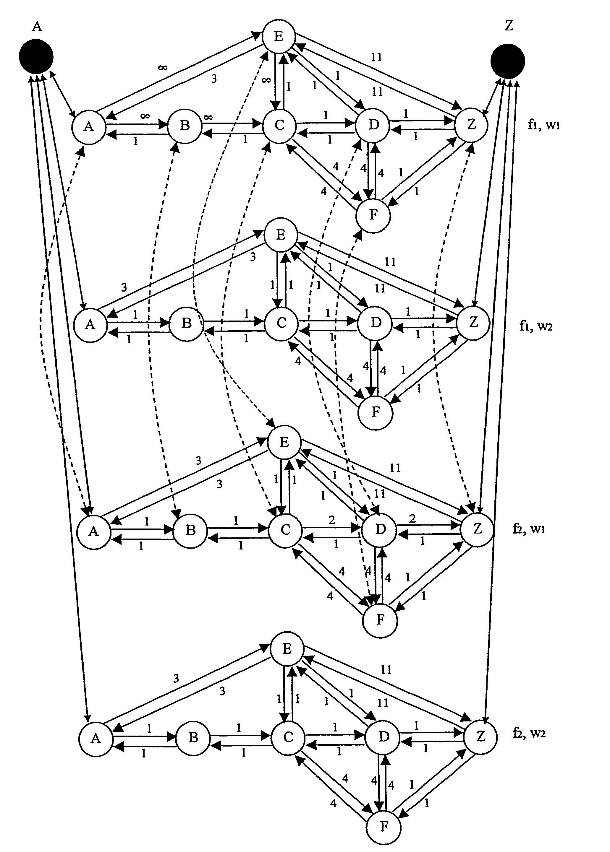
[0087]FIG. 6a shows the layered graph representing the network of FIG. 5 in this case. The layered graph has four layers corresponding to the labeling pairs (f1,w1), (f1,w2), (f2,w1), (f2,w2). Bidirectional horizontal arcs between image nodes are reported in each layer, representing the links between the nodes of the network of FIG. 5. Bidirectional vertical arcs connect corresponding image nodes belonging to the layers labeled with the same wavelength and a different fiber, representing the capability of fiber switching in each node. For the sake of simplicity, in FIG. 6a only the vertical arcs connec...

case 2

twork—Edge-disjoint

[0109]In a VWP network all the nodes have wavelength conversion capability. Thus, each lightpath (working or spare) associated to a connection request may use more than one wavelength.

[0110]FIG. 7a shows the layered graph representing the network of FIG. 5 in this case. Differently for the WP case, bidirectional vertical arcs connect corresponding image nodes with each other in all the layers, representing both the possibility of wavelength conversion and of fiber switching in each node. For the sake of simplicity, in FIG. 7a only the vertical arcs connecting corresponding image nodes A and B have been shown. However, it has to be intended that similar arcs should connect with each other all the corresponding nodes in all the layers. “Oblique” arcs are still forbidden. For the sake of simplicity, add-drop function was shown in FIG. 7a only for the two source-destination image nodes A-Z. This has not to be intended as limiting the invention, in that any of the node...

case 3

etwork—Edge-disjoint

[0125]In a PVWP network only some of the nodes have wavelength conversion capability. Thus, a lightpath (working or spare) associated to a connection request may use more than one wavelength.

[0126]FIG. 8a shows the layered graph representing the network of FIG. 5 in this case. For exemplary purposes, it is assumed that the two adjacent nodes C and D have wavelength conversion capability. These nodes have been highlighted with punctuation in FIG. 8a. Bidirectional vertical arcs have not been shown in FIG. 8a for simplicity. However, it has to be intended that bidirectional vertical arcs connect corresponding image nodes C and D with each other, respectively, in all the layers, representing both the possibility of wavelength conversion and of fiber switching. As far as the other nodes are concerned, bidirectional vertical arcs connect corresponding image nodes belonging to the layers labeled with the same wavelength and a different fiber, representing the capabilit...


PUM


Abstract

A tool for static or dynamic planning of a WDM network with dedicated protection. The WDM network is represented by a layered graph having image nodes for each node of the network and horizontal arcs for each link of the network, so as to replicate in each layer the topology of the network. A Bhandari algorithm is adapted for finding on the layered graph a working-spare pair of lightpaths for each connection request to be allocated.

Description

CROSS REFERENCE TO RELATED APPLICATIONS[0001]This application is a national phase application based on PCT / EP02 / 13071, filed Nov. 21, 2002, the content of which is incorporated herein by reference, and claims the priority of European Patent Application No. 01128616.8, filed Nov. 30, 2001, and claims the benefit of U.S. Provisional Application Ser. No. 60 / 337,138, filed Dec. 10, 2001.BACKGROUND OF THE INVENTION[0002]1. Field of the Invention[0003]The present invention relates a method for planning or provisioning data transport networks, in particular optical networks employing wavelength division multiplexing (WDM).[0004]2. Description of the Related Art[0005]Transport networks are wide area networks that provide connectivity for aggregated traffic streams. Modern transport networks increasingly employ wavelength division multiplexing (WDM) technology to utilize the vast transmission bandwidth of optical fiber. WDM is based on transmission of data over separate wavelength channels o...

Claims


Application Information

Patent Timeline
IPC IPC(8): H04J14/00H04L12/28H04J14/02H04Q11/00
CPCH04J14/0227H04J14/0294H04Q11/0062H04J14/0249H04J14/0241H04J14/0245H04J14/0284H04Q2011/0073H04Q2011/0086
Inventor DE PATRE, SIMONEMAIER, GUIDO ALBERTOPATTAVINA, ACHILLE
Owner TELECOM ITALIA SPA
Why Eureka
Try Eureka