Method and apparatus for performing wide area terrain mapping

a wide-area, terrain mapping technology, applied in the field of imaging systems, can solve the problems of large labor intensity, high cost of scanning lidar instruments, and high cost of process

Active Publication Date: 2008-04-22
SRI INTERNATIONAL
View PDF9 Cites 128 Cited by
  • Summary
  • Abstract
  • Description
  • Claims
  • Application Information

AI Technical Summary

Benefits of technology

[0008]The present invention is a method and apparatus for performing wide area terrain mapping. The system comprises a digital elevation map (DEM) and mosaic generation engine that processes images that are simultaneously captured by an electro-optical camera (RGB camera) and a LI

Problems solved by technology

However, commercial scanning LIDAR instruments are relatively expensive and bulky such that aerial imagery (video imagery) must be acquired separately and t

Method used


Image

  • Method and apparatus for performing wide area terrain mapping
  • Method and apparatus for performing wide area terrain mapping
  • Method and apparatus for performing wide area terrain mapping

Examples


Embodiment Construction

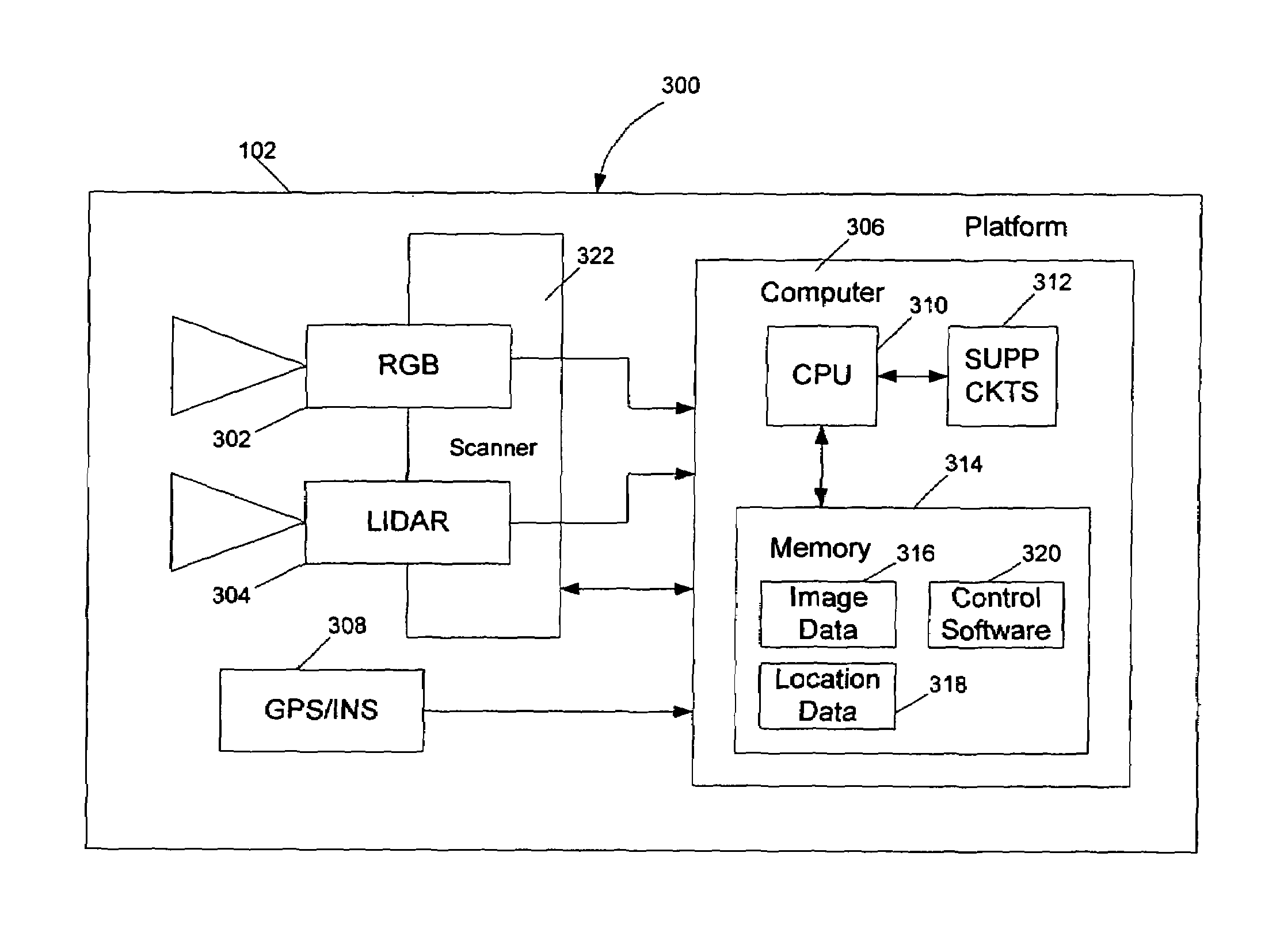
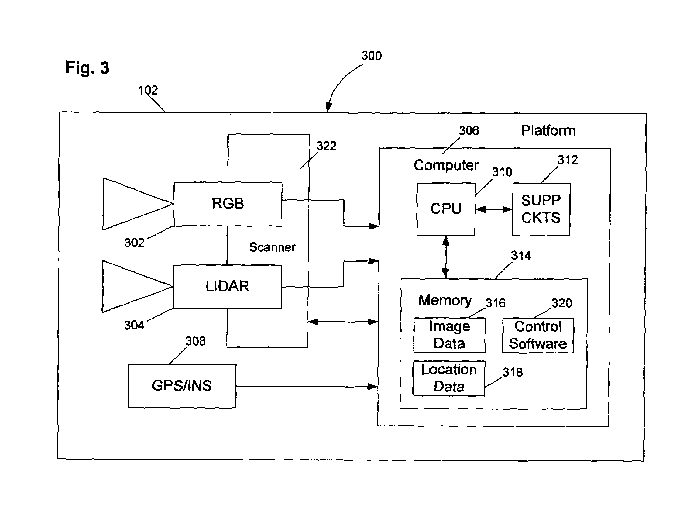
[0017]The present invention is a method and apparatus for performing wide area terrain mapping using a combination of LIDAR and video technology within a single platform.

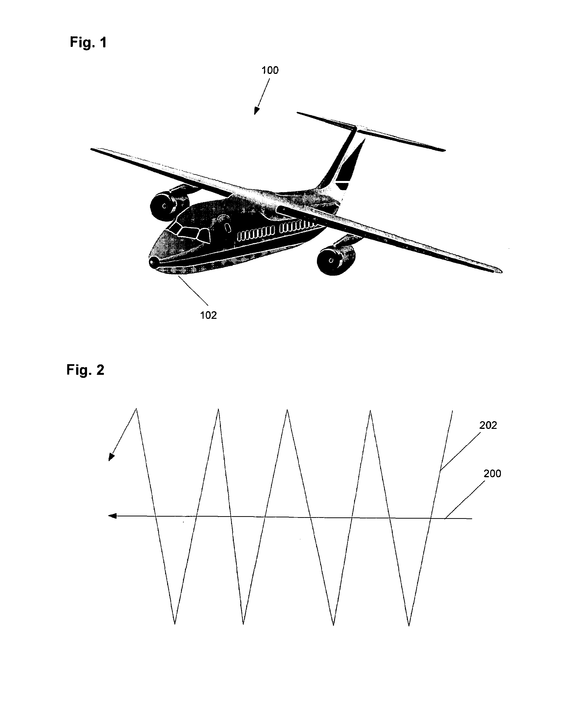
[0018]FIG. 1 depicts an aerial platform 100 that carries a sensor suite 102 that performs aerial imaging of objects on the ground. The platform 100 may be a manned airplane or helicopter, or the platform 100 may be an unmanned aerial vehicle (UAV). Whatever form the platform takes, the suite 100 is used to collect range data, video imagery, and metadata comprising the location of the platform (e.g., Universal Transverse Mercator (UTM) coordinates) and the orientation of the sensor suite 102 (e.g., a scan angle). This information is stored within the sensor suite 102 for subsequent processing. Of course, the information could also be transmitted to a ground station (not shown) for processing.

[0019]FIG. 2 depicts a flight path 200 that is flown by the aerial platform while the sensor suite 102 is performing a scan pat...


PUM


Abstract

A method and apparatus for performing wide area terrain mapping. The system comprises a digital elevation map (DEM) and mosaic generation engine that processes images that are simultaneously captured by an electro-optical camera (RGB camera) and a LIDAR sensor. The image data collected by both the camera and the LIDAR sensor are processed to create a geometrically accurate three-dimensional view of objects viewed from an aerial platform.

Description

CROSS-REFERENCE TO RELATED APPLICATIONS[0001]This application claims benefit of U.S. provisional patent application Ser. No. 60 / 651,685, filed Feb. 10, 2005, which is incorporated by reference.GOVERNMENT RIGHTS IN THIS INVENTION[0002]This invention was made with U.S. government support under contract number GS-10F-0197L-84658. The U.S. government has certain rights in this invention.BACKGROUND OF THE INVENTION[0003]1. Field of the Invention[0004]Embodiments of the present invention generally relate to an imaging system and, more particularly, the present invention relates to wide area terrain mapping.[0005]2. Description of the Related Art[0006]The geographic system industry has begun to exploit scanning LIDAR (Light Detection and Ranging) techniques to directly collect three-dimensional topography. Typically, a single laser beam is moved over the ground using aircraft motion and scanning mirrors. Using a measure of the time of flight for each pulse of a laser, range from the laser ...

Claims


Application Information

Patent Timeline
IPC IPC(8): G06F7/22
CPCG01C11/00G01S17/023G01S17/89G01S17/86
Inventor HANNA, BARBARACHAI, BING-BINGHSU, STEPHEN
Owner SRI INTERNATIONAL
Why Eureka
Try Eureka